Page 8-70 LTV
®
1200/1150 Ventilator Service Manual p/n 18603-001, Rev. C
15) Select the VHome setting printed on the VHome label of the flow valve.
16) Enter the TEMP COMP menu and make sure that temperature compensation is set to
TCOMP ON.
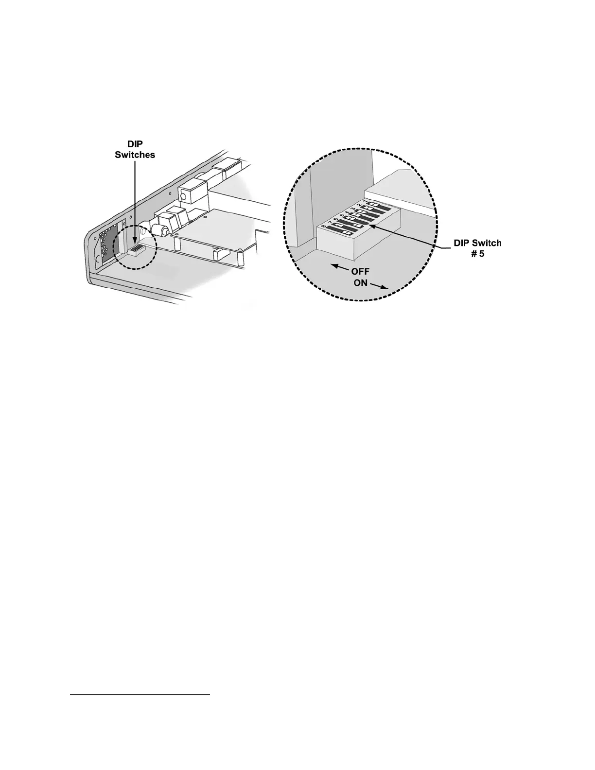
17) Power the ventilator off and set dip switch 5 to the OFF position (see instructions on
page 6-5).
18) Install an O
2
Sampling Tube
47
. See Back Panel, Reinstallation in Chapter 8 –
Component Removal and Replacement for detailed instructions.
19) Verify that no tubing is kinked or twisted, and that it will not be pinched when
compressed by the back panel. Refer to the configuration instructions, tables and
diagrams beginning on page 8-33 to check the tubing routing. Always check ALL tube
routing for kinks or compression that might result in restricted flows prior to closing the
ventilator.
20) Reconnect the internal battery and replace the back panel (see page 8-29).
47
O
2
Sampling Tube, P/N 10544, ~10.0” long, 0.125” O.D. X 0.079 I.D. clear polycarbonate tubing.