p/n 18603-001, Rev. C LTV
®
1200/1150 Ventilator Service Manual Page 8-69
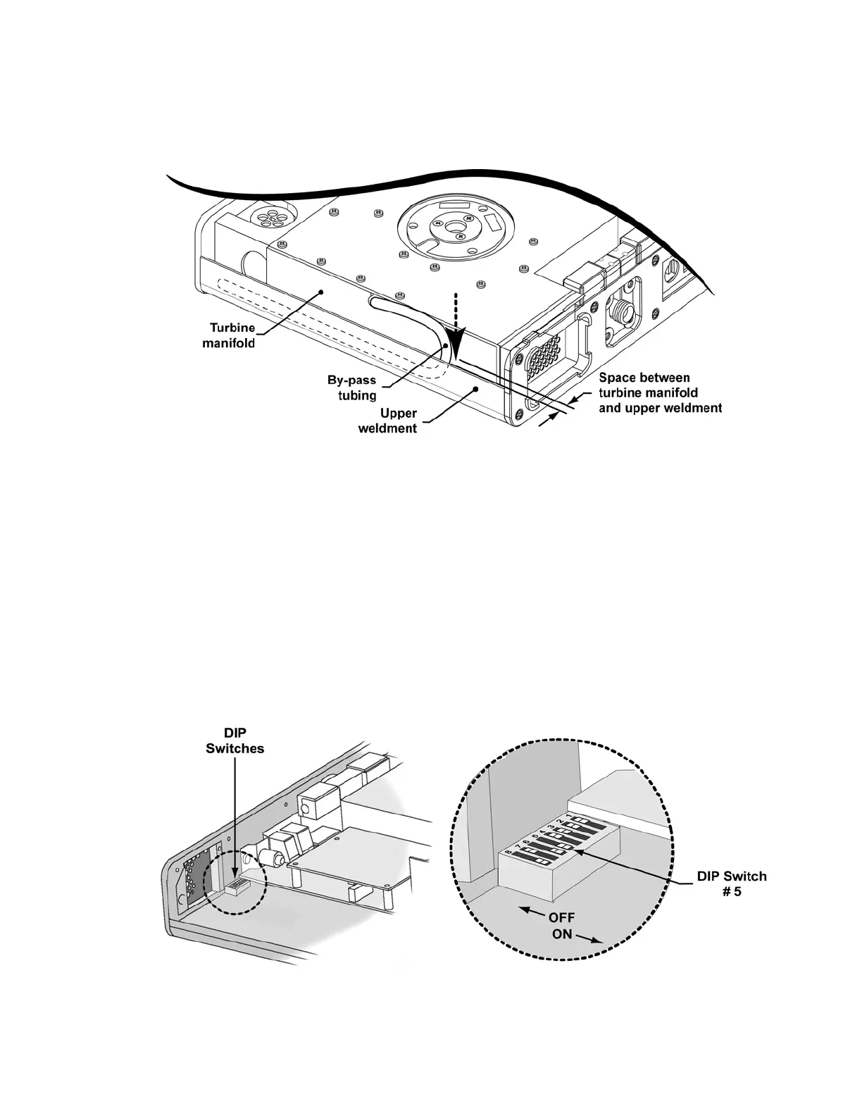
8) Loop the bypass tubing down into the space between the manifold and the bottom edge
of the upper weldment as shown so that it will not be pinched when the back of the
ventilator is replaced.
9) Connect the orange tube to the valve differential transducer low pressure port on the
analog board (furthest from the board).
10) Connect the clear flexible tube from the flow valve to port #5 on the solenoid manifold.
See internal flexible tube routing tables, instructions and diagrams on page 8-33.
11) Connect the 3-wire connector to the power board and the 4-wire connector to the motor
board. Both connectors are keyed to install in one direction only and will snap into place
when properly connected.
12) Reconnect the Pisco connector to the oxygen pressure transducer on the analog board
(LTV
®
1200 only). See internal flexible tube routing tables, instructions and diagrams on
page 8-33.
13) Reconnect the internal battery (see instructions on page 8-29).
14) Set dip switch 5 to the ON position, power up the ventilator and enter the FLOW
VALVE menu (see instructions on page 6-35.)