MAINTENANCE/SERVICE
Header
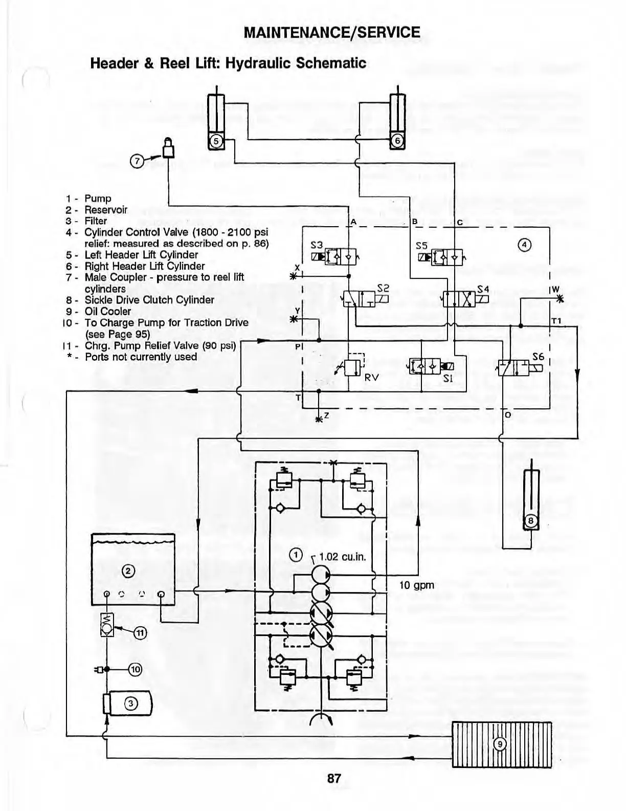
& Reel Lift: Hydraulic Schematic
1 -
Pump
2 -
Reservoir
3 - Filter
t--
~
l
'---------<;-'1.
·
L-
________
~----~
4 - Cylinder Control Valve (1800 - 2100 psi
relief: measured as described on p. 86)
5 -
Left
Header Uft Cylinder
6 - Right Header
Uft
Cylinder
7 - Male Coupler - pressure to reel lift
cylinders
S2
S4
IW
8 - Sickle Drive Clutch Cylinder
9 - Oil Cooler
10
-
To
Charge Pump for Traction
Drive
1
X~
y
(see
Page
95)
,
11
-
Chrg
.
Pump
Relief
Valve
(90
psi)
'---;;'"1
.....
---r-----r-~
!----,
1
• -
Ports
not currently used 1
m:
j(
I
4-
itZJ
1.±-1rll.n.cLmS~6
1
r-
__________
~--~----~T~~~~-~L_-:-V===-_~_-S=l~
__
~
0)
z 0
,
'----
-:;, I
r
-=.--
T I
~
---(-J,~=--::j
87
I""
9
T1