MAINTENANCE/SERVICE
Header Drive: Hydraulics
FLOW
COmRQL
BlOCK
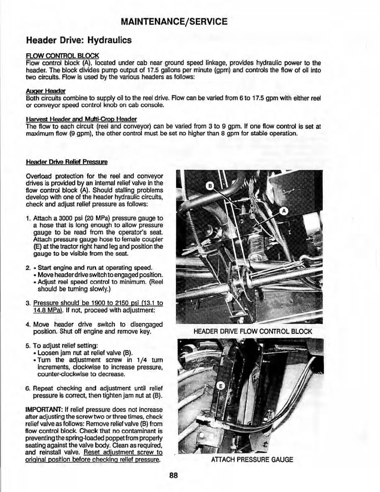
Row control block (Al.
located
under cab near ground
speed
linkage, provides hydraulic power to the
header.
The
block dMdes pump output
of
17
.5 gallons per minute (gpm)
and
controls the
flow
of
on
into
two circuits.
Row
Is
used
by
the various headers
as
follows:
AlxmHeader
Both circuits combine
to
supply
oil
to the
reel
drive. Row
can
be
varied from 6 to
17
.5 gpm with either
reel
or
conveyor speed control knob on cab console.
Harm;!
Header
and
MIIti-Croo
Header
The
flow
to
each circuit
(r
eel
and conveyor) can
be
varied from 3
to
9 9pm. If one flow control
Is
set at
maximum flow
(9
gpm), the other control must be
set
no
higher than 8 gpm for stable operation.
Head
...
OrNe
Relief
Pressure
Overtoad protection for the
reel
and conveyor
drives
Is
provided by
an
internal relief
valve
in
the
flow control block
(A)
. Should stalling problems
develop with
one
of the header hydraulic circuits,
check
and
adjust relief pre
ss
ure
as
follows:
1. Attach a
3000
psi
(20
MPa)
pr
essu
re
gauge to
a hose
that is long enough to allow pr
essu
re
gauge to
be
read from
the
operator's
seat.
Attach pressure gauge hose to
female
coupler
(E)
at the tractor right hand leg
and
position
the
gauge
to
be
visible from the
seat.
2 . • Start engine and
run.
at operating
speed.
• Move header drive switch to engaged position.
• Adjust reel
speed
control to minimum.
(Reel
should
be
tuming
slow1y
.)
3.
Pres
sure
should
be
1900
to
2150
psi
(13.1 to
14
.8
MP
a).
If not, proceed with adjustment:
4.
Move header drive switch to disengaged
position.
Shut off engine
and
remove
key.
5.
To adjust relief setting:
• Loosen jam nut at relief
valve
(8).
• Tum the adjustment screw
in
1/ 4 tum
increments. clockwl
se
to inc
rease
pre
ssu
re
,
counter-dockw
ise
to
decrease.
6. Repeat checking and adjustment until
relief
pressurels correct, then tighten jam
nut
at
(6).
IMPORTANT:
If
rel
ief pressure d
oes
no
t increase
after adjusting the screw two or three
times,
check
relief valve
as
fol
lows: Remove relief
valve
(8) from
flow control block. Check that no contaminant
is
preventing the spring-loaded poppet from properly
seating against the valve
body.
Clean
as
required,
and reinstall
valve
.
Re
se
t adlustment screw to
original position before checking
relief pressure.
HEADER
DRIVE
FLOW
COmROL
BLOCK
ATIACH
PRESSURE
GAUGE
88