OPERATION
Attaching the Header
NOTE:
For
Ha
rvest Headers with gauge
wheels,
in
structions under "Attaching" and
"Oetaching the H
eader"
which refer to the
"header stand" do not apply. U
se
the "stand"
position of the gauge
wheels
to support rear of
header.
All
gauge
wheel
positio
ns
are
identified
on a decal located at each gauge wheel. Be
sure to reposition
gauge
whee
l to
field
position
before operating.
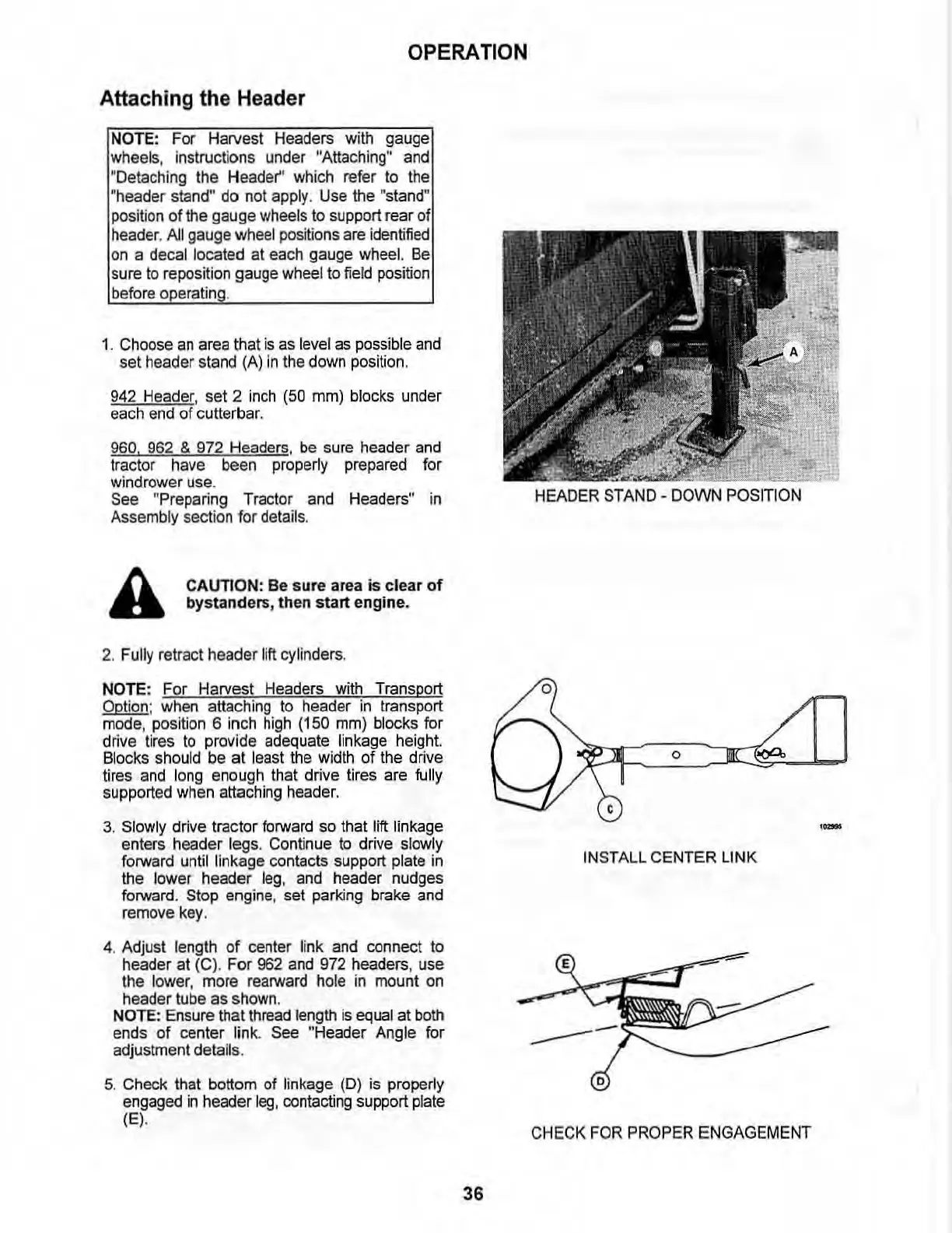
1.
Choose
an
area
that
is
as
level
as
possible
and
set
header stand (
A)
in
the down position.
942
He
ader, set 2
inch
(50
mm) blocks under
each
end
of cutterbar.
960.
962
&
972
Headers, be sure header
and
tractor
have
been
properly
prepared
for
wind
rower
use
.
See
"Preparing T
ractor
and
Headers" in
Assembly secti
on
for
details.
A
CAUTION:
Be
sure
area is clear
of
bystanders
, then
start
engine.
2. Fully retract header lift cylinders.
NOTE: For Harvest Headers with Transport
Opti
on
: when attaching
to
header
in
transport
mode, position 6 inch
high
(150 mm) blocks for
drive tires
to
provide adequate linkage height.
Blocks should be at least the width of the drive
tires
and
long enough that drive tires are fully
supported when attaching header.
3. Slowly drive tractor forward so that
Jift
linkage
enters header legs. Continue
to
drive slowly
forward until linkage contacts support plate
in
the lower header
leg
,
and
header nudges
forward. Stop engine, set parking brake
and
remove key.
4. Adjust length
of
center link
and
connect to
header at (C). For
962
and 972 headers, use
the lower, more rearward hole
in
mount on
header tube as shown.
NOTE
: Ensure that thread length
is
equal at both
ends
of
center l
in
k.
See
"Header Angle for
adjustment details.
5. Check that bottom of linkage (D)
is
proper1y
engaged
in
header
leg,
contacting support plate
(EI
·
36
HEADER
STAND
-
DOWN
POSITION
o
o
c
IN
STALL
CEN
TER LINK
C
HECK
FOR
PROPER
ENGAGEMENT