ASSEMBLY
N
OT
E: The purpose of shipping preparations
such
as
having
no
battery
is to better adapt
the
unit for
an
extended non-active
period
. If the machine
is
to
rema
in non-active for a
long
period of time,
do
not
perfonn
the following
assembly work until necessary. Also, further prepare
the
un
it for storage
as
instructed
in
th
is
manual.
Tires
1
6.
5 REAR
TIR
ES Install
as
follows:
1.
Lift
rear
end
of
wind rower
with
forklift and
remove yellow shipping support
from
walking
beam. Replace bolts securing walki
ng
beam
pivot tube bracket
and
torque
to
390
N·m
(290
ft
.lbs.).
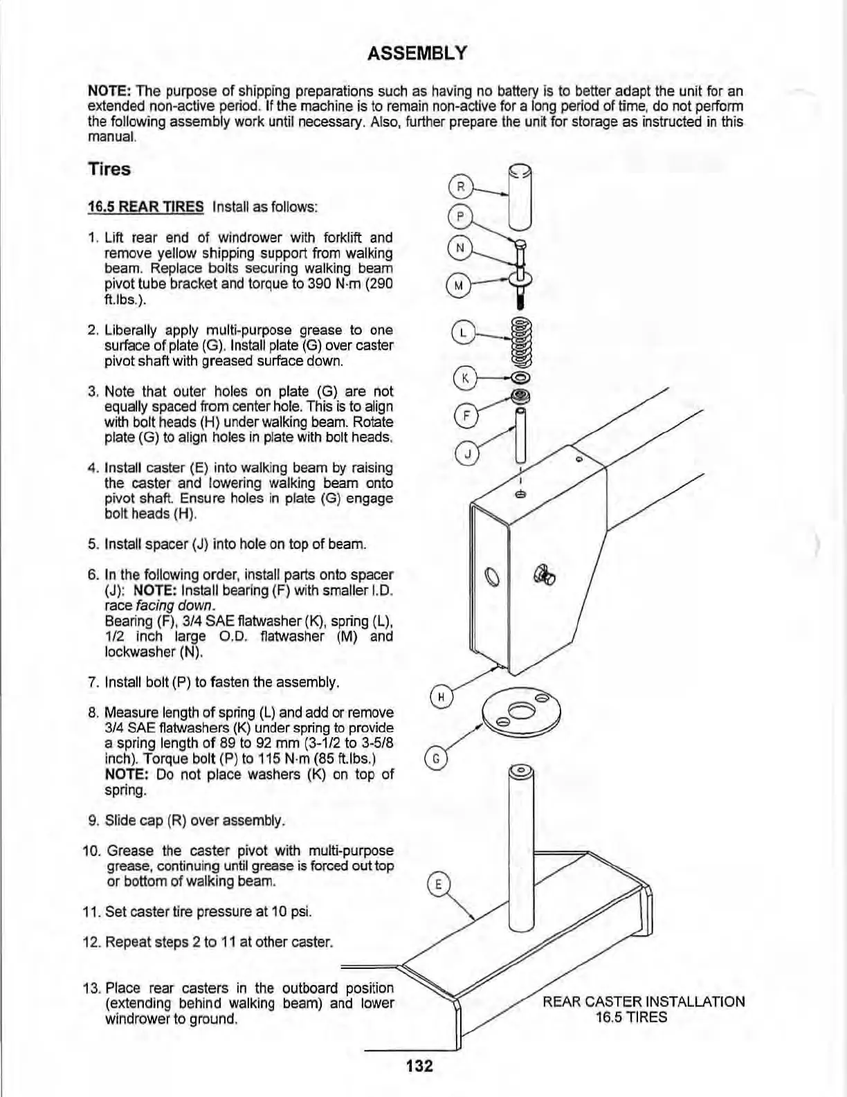
2. Liberally apply multi-purpose grease to
one
surface
of
plate
(G). I
nstall
pl
ate
(G)
over
caste
r
pivot shaft
with
greased surface
down.
3. Note that outer
holes
on
plate
(G)
are not
equally
spaced
from center
ho
l
e.
This
is
to
align
with
bolt
heads
(H) under
walking
beam.
Rotate
pla
te (G) to align holes
in
plate
wi
th bolt
heads
.
4.
Install
ca
ster
(E
l into walki
ng
bea
m
by
raising
the caster and
lowering walking
beam
onto
pivot shaft.
En
sure holes in plate (G) engage
bo
lt heads (H).
5.
In
stall spacer (J) into
hole
on
top of
beam
.
6.
In
the
fonowing
order, install parts onto spacer
(J):
NOTE: Install bearing (F) with smaller 1
.0
.
race
facing down.
Beanng
(F)
, 3/4
SAE
flalwasher
(I<)
,
spnng
(L)
,
112
inch large 0 .0. flatwasher
(M)
and
lockwasher
(N).
7. Install bolt
(P)
to fasten the assembly.
8. M
easu
re
length
of
spring
(L)
and add
or
remove
3/4
SAE
flatwashers
(K)
under
sp
ri
ng
to provide
a spring length of
89
to
92
mm
(3-1/2
to
3-518
inch
).
Torque
bol
t
(P
)
to
115
N·m
(85
ft.lbs.)
NOTE:
Do
not place washers
(K)
on
top of
spring.
9.
Sli
de
cap
(R)
over assembly.
10. Grease the caster pivot with multi-purpose
grease, contin
uing
u
ntil
gr
ease
is
forced
out top
or bottom of walking
beam
.
11
. Set caster
ti
re pressure at
10
psi.
1
2.
Repeat steps 2 to
11
at other caster.
13
.
Place
rear
casters
in
the outboard position
(extending behind
walking
beam)
and
lower
wind
rower to ground.
132
~
N
"
~
~
~
,
'"
0
REAR
CASTER
I
NS
TAL
LATION
16.5
TI
RES