MAINTENANCE/SERVICE
Hydraulic
System: Header &
Reel
Lift
CYUNDER
CONTROL
VALVE
REUEF
PRESSURE
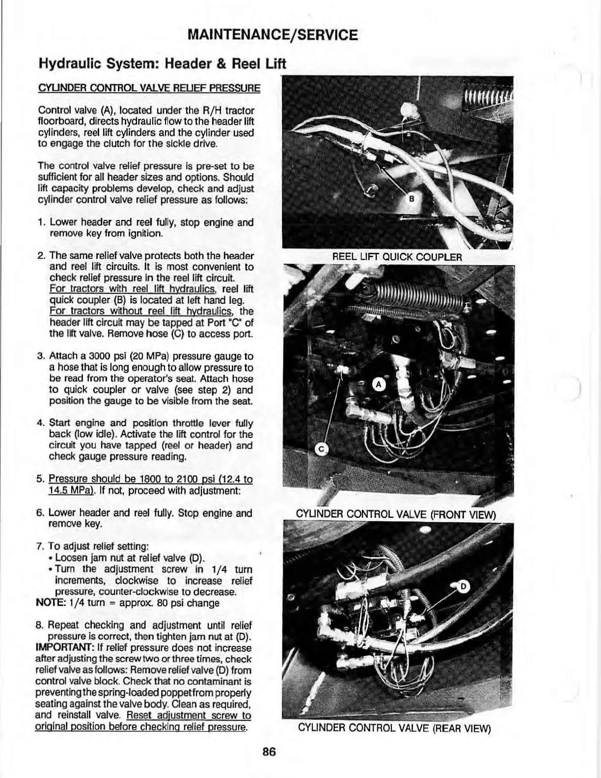
Control valve
(A),
located under the
RjH
tractor
floorboard, directs hydraulic
flow
to the header lift
cylinde
rs,
reel lift cylinders and the cylinder used
to
engage the clutch for
the
sickle drive.
The control valve
relief pressure is pre-set
to
be
sufficient
for
all header sizes and options. Should
lift
capacity
prob
l
ems
deve
l
op
,
check
and
adjust
cyli
nder
control
valve
relief
pre
ss
ure
as
follows:
1. Lower header and reel fully. stop engine and
remove key from ignition.
2.
The
same
relief
valve
protects both the
header
and
reel
lift circuits. It
[s
most convenient
to
check relief pressure In the reel lift circuit.
For tractors with
reel
lift hydraulics.
reel
lift
qu
ick coupler (6) is located at left hand leg.
For tractors without reel lift hydraulics. the
header litt circuit may
be
tapped at Port
.C"
of
the
11ft
valve. Remove hose (e)
to
access port.
3. Attach a
3000 psi
(20
MPa) pressure gauge
to
a hose that is long enough
to
allow pressure
to
be
read from the operator's seat. Attach hose
to
quick coupler
or
valve (see step
2)
and
position the gauge to
be
visible from the seat.
4.
Start engine and position throttle lever fully
back
~ow
idle). Activate the lift control for the
circuit you have tapped (reel
or
header) and
check gauge pressure reading.
5. Pressure should be
1800
to
2100 psi (12.4
to
14.5 MPal. If
not
, proceed with adjustment
6. Lower header and reel fully.
Stop engine and
remove key.
7. To adjust relief setting:
• Loosen jam nut at relief
val
ve (D) .
• Tum the adjustment screw
in
1/ 4 tum
increments. clockwise to increase relief
pressure, counter-clockwise
to
decrease.
NOTE:
1/4
turn = approx.
80
psi change
8. Repeat checking and adjustment until
relief
pressure is correct, then tighten jam nut at
(D)
.
IMPORTANT:
If
relief pressure does
not
increase
after adjusting the screw
two
or
three times. check
relief valve as follows: Remove relief valve (0) from
control valve block. Check that no contaminant is
preventing the spring-loaded poppet from properly
seating against the
valve
body
. Clean as required,
and reinstall valve.
Re
set adjustment screw
to
original position before checking relief Dressure.
86
REEL
UFT
QUICK
COUPLER
)