169441 153 Revision D
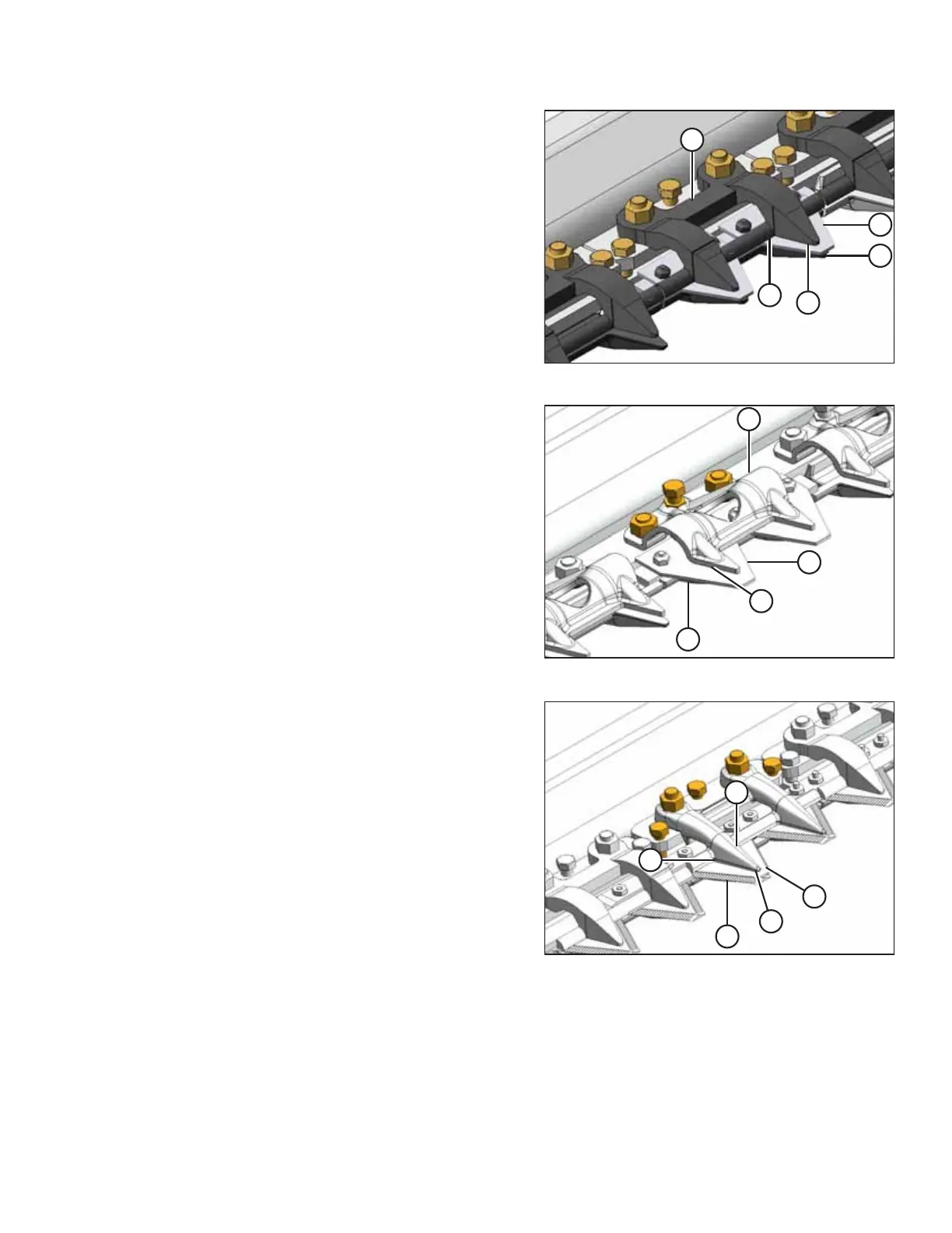
Figure 4.65: Short Knife Forged Hold-Down
Figure 4.66: Short Knife Sheet Metal Hold-Down
2. Manually stroke knife to locate section under
hold-down (A).
3. Standard guard: At standard guard locations, push knife
section (B) down against guard (C) and measure clearance
between hold-down clip (A) and knife section (B) with a
feeler gauge. The clearance should be as follows:
• At hold-down tip (D): 0.1–0.4 mm (0.004–0.016 in.)
• At rear of hold-down (E): 0.1–1.0 mm (0.004–0.040 in.)
• At sheet metal hold-down (F): 0.1–0.6 mm (0.004–
0.024 in.)
4. If necessary, refer to Adjusting Stub Guard Hold-Downs,
page 155.
Figure 4.67: Double-Knife Center Short Knife Guard
Hold-Down
5. Double-knife center stub guard: Manually stroke the knife
to locate sections under hold-down (B). Measure clearance
between knife sections (A) and (C) with a feeler gauge. The
clearance should be as follows:
• At hold-down tip (D): 0.1–0.4 mm (0.004–0.016 in.)
• At rear of hold-down (E): 0.1–1.0 mm (0.004–0.040 in.)
6. If necessary, refer to Adjusting Stub Guard Hold-Downs,
page 155.
Adjusting Pointed Guard Hold-Downs
This procedure is applicable to formed sheet metal hold-downs. Do NOT use this procedure for the hold-down at the
center guard position where knives overlap on double-knife headers.
For the center guard, refer to Adjusting Hold-Down Clips at Double-Knife Center Pointed Guard, page 154.
MAINTENANCE AND SERVICING