169441 273 Revision D
Table 7.8 O-Ring Boss (ORB) Hydraulic Fittings – Non-Adjustable (continued)
SAE Dash Size
Thread Size (in.)
Torque Value
12
Nm
lbf·ft (*lbf·in)
-10
7/8–14
75–82 55–60
-12
1 1/16–12
120–132 88–97
-14
1 3/8–12
153–168 113–124
-16
1 5/16–12
176–193 130–142
-20
1 5/8–12
221–243 163–179
-24
1 7/8–12
270–298 199–220
-32
2 1/2–12
332–365 245–269
7.2.5 O-Ring Face Seal Hydraulic Fittings
The standard torque values are provided for O-ring face seal hydraulic fittings. If a procedure specifies a different torque
value for the same type and size of fitting found in this topic, refer to the value specified in the procedure instead.
Torque values are shown in the Table 7.9, page 274.
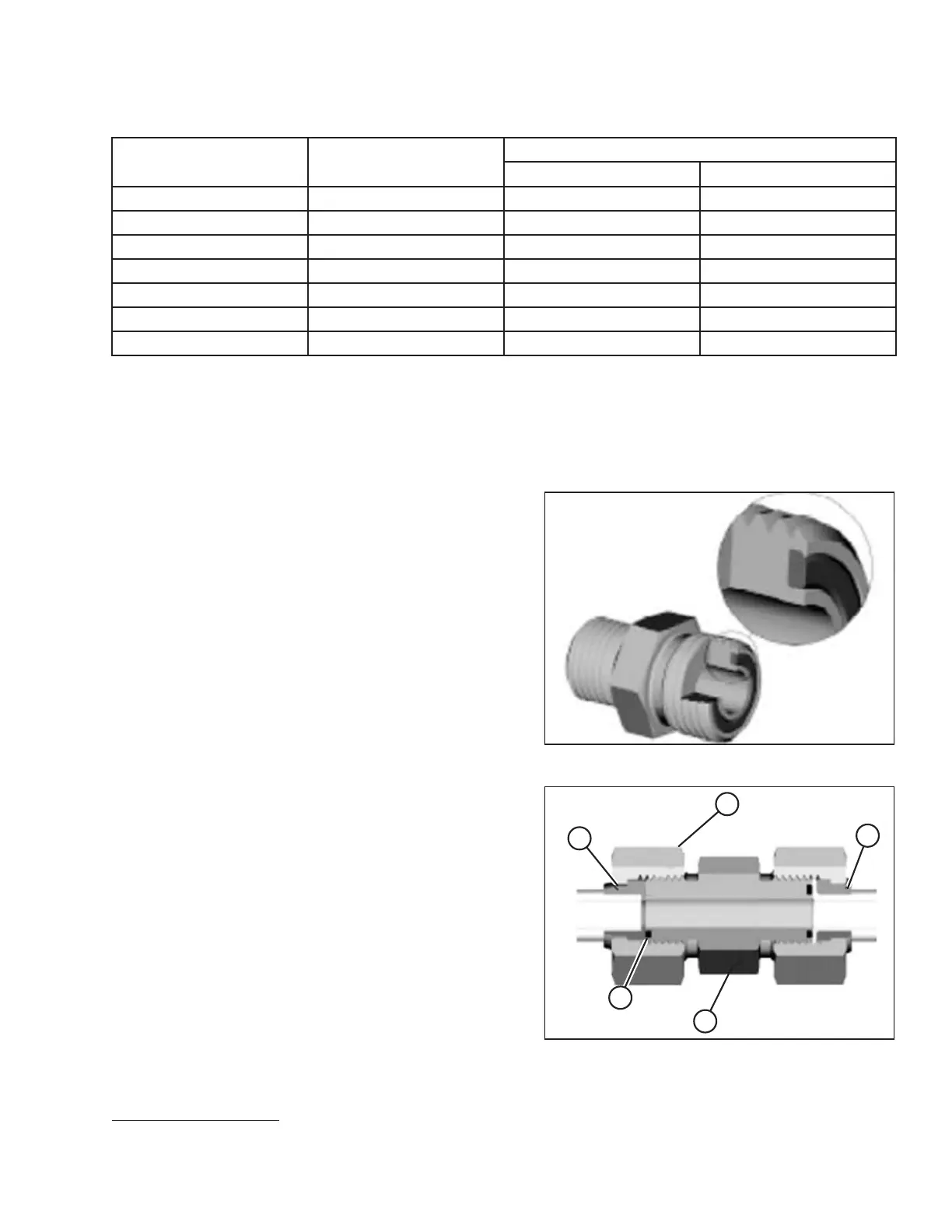
Figure 7.9: Hydraulic Fitting
1. Ensure that the sealing surfaces and the fitting threads are
free of burrs, nicks, scratches, and any foreign material.
Figure 7.10: Hydraulic Fitting
2. Apply hydraulic system oil to O-ring (B).
3. Align the tube or hose assembly so that the flat face of
sleeve (A) or (C) comes into full contact with O-ring (B).
4. Thread tube or hose nut (D) until it is hand-tight. The nut
should turn freely until it bottoms out.
5. Torque the fittings according to values in Table 7.9, page
274.
NOTE:
If applicable, hold the hex flange on fitting body (E) to
prevent the rotation of the fitting body and the hose when
tightening fitting nut (D).
REFERENCE
12. Torque values shown are based on lubricated connections as in reassembly.