ASSEMBLY/SETUP IN STRUC TIONS
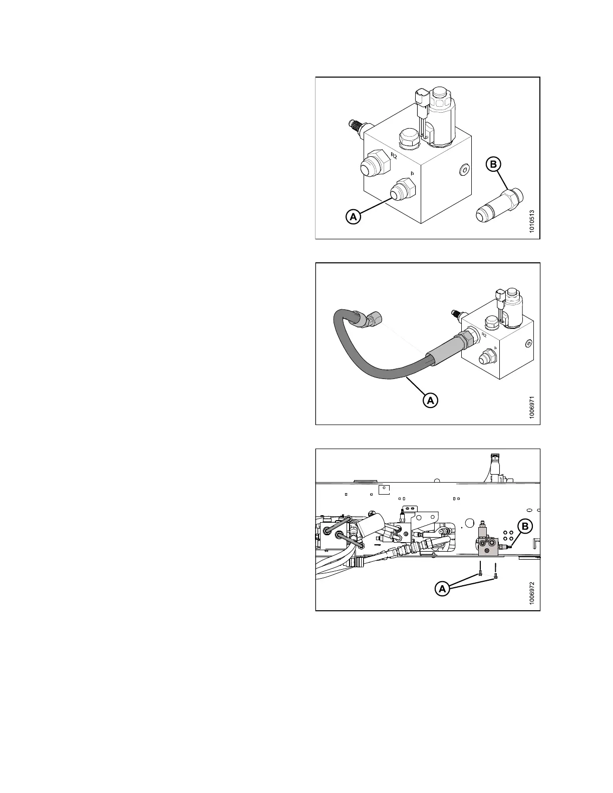
3. Select the correct fitting for your windrower model.
• For M150/M200: install the regular #10 ORB x #10
JIC fitting (A) in port P on DWA drive manifold.
• For M155/M155 E4 /M205: install the long #10 ORB
x#10JICfitting (B) in port P on DWA drive manifold.
Figure 2.5: DWA Driv e Manifold
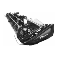
4. To simp lify assembly, install ho se (A), supplied in kit,
to th e fittinginportR2ofDWAdrivemanifoldbefore
attaching the manifold to the fra me.
Figure 2.6: DWA Driv e Manifold
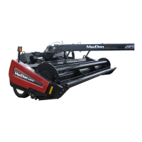
5. Attach the DWA dr ive ma nifold to the windrower
left-hand side frame with two 3/8 in. serrated flange
head bolt s (A). Route hose an d fittings through side
frame pointing toward the windrower engine and relief
valve (B) pointing to rear of windrower.
NOTE:
Leave
plugs in ports DWA and R1.
Figure 2.7: Windrower Left-Hand Side
(M205 Shown)
214049
14
Revision A


 To Next Page