ASSEMBLY/SETUP INSTRUCTIONS
10. Position two 1-1/2 in. OD x 1 in. ID x 2-3/4 in. long
spacers (A) on the rear bolts.
NOTE:
Spacers are n ot required with the linkage in the
rearward position.
11. Attach the linkage with four flat washers, lock washers,
and nuts (B).
Figure 2.33: Linkage Forward
12. Lower linkage by pullin g on safety pin (A) on the
left-hand side of linkage.
13. If the linkage does not lower, remove plugs at the end
of lift cylinder hoses (B) to remove air from hoses.
Figure 2.34: DWA Linkage
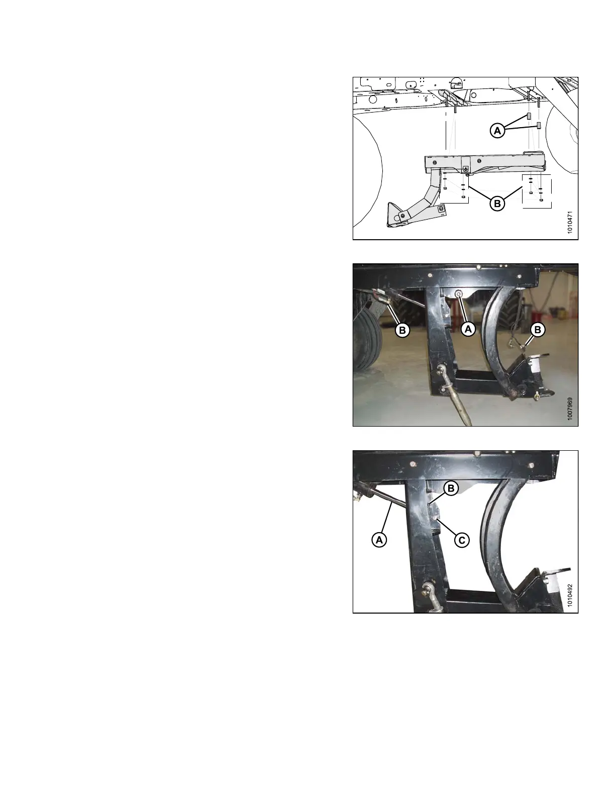
14. Secure the lift cylinder pivot (A) into the correct hole
depending on header type:
• For R-Series Header: insert pin in the upper hole (B)
• For D-Series or A-Series Headers: insert pin in the
lower hole (C)
Figure 2.35: Lift Cylinder Pivot
214049 25 Revision A
 Loading...


