ASSEMBLY/SETUP INSTRUCTIONS
M205 Windrower (2010 and 2011 Production
Year Only):
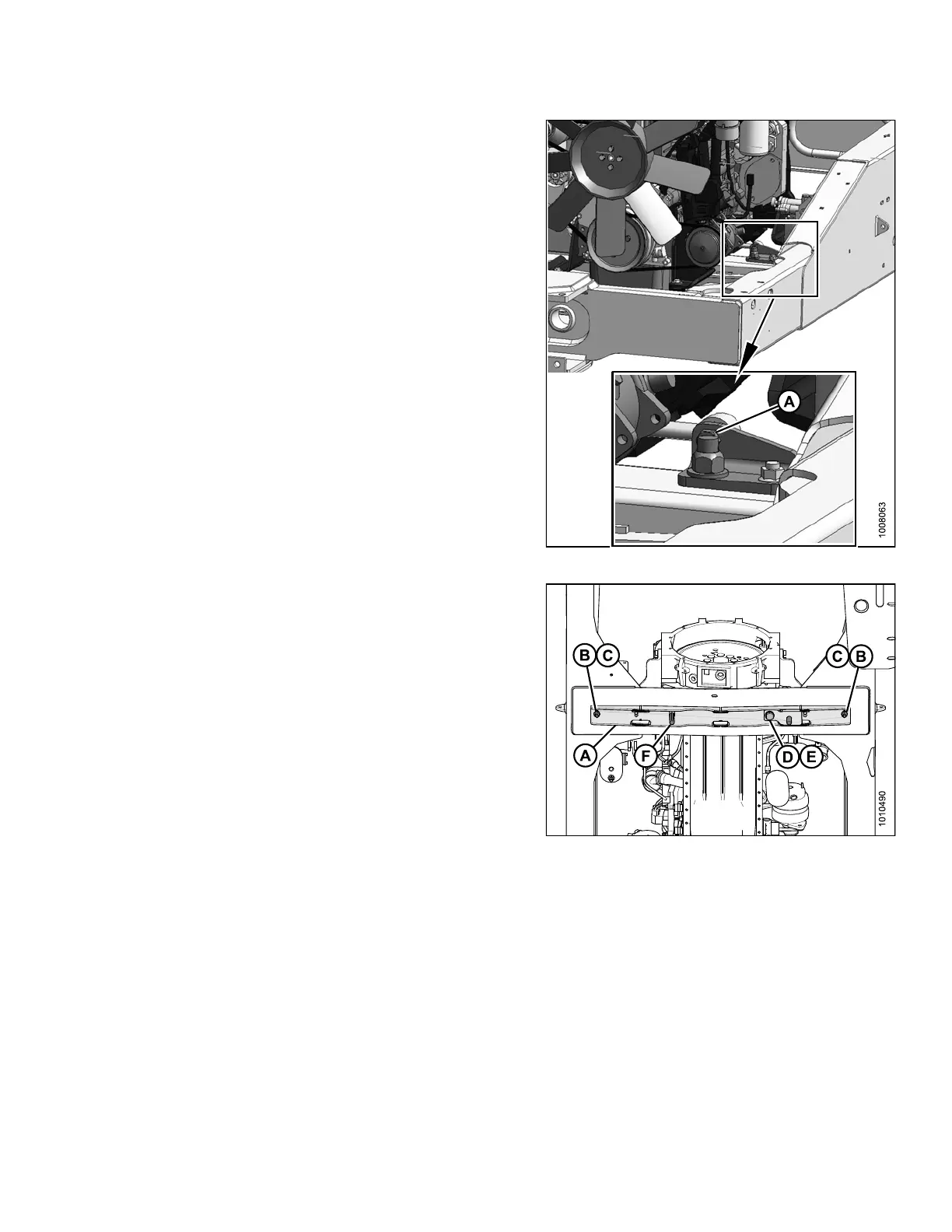
3. Remove the 3/4 in. x 3-1/2 in. long bolt (A) from the
stabilizer link mou nt near the right front en g ine mou nt.
Retain bolt for reuse.
Figure 2.
38: Stabilizer Link
4. Mount the linkage support (A) to the windrower frame
with two 1/2 in. x 2-3/4 in. long hex head bolts (B)
with flat washers under the bolt heads and secure with
nuts (C).
5. From below the support, install a 3/4 in. x 3-1/2 in. long
hex head bolt (D) witha flat washer under thebolt head.
6. Secure with a flat washer, a lock washer, and a nut on
top side of the frame.
7. From above the support, install a 3/4 in. x 5-1/2 in. long
hex head bolt (F) with flat washer under the bolt head.
NOTE:
This
bolt replaces the 3-1/2 in. long bolt removed
in St
ep 3., page 27.
Do NOT install nut on bolt (F).
Figur
e 2.39: Linkage Support
214049
27
Revision A
 Loading...


