215620 197 Revision A
DANGER
Ensure that all bystanders have cleared the area.
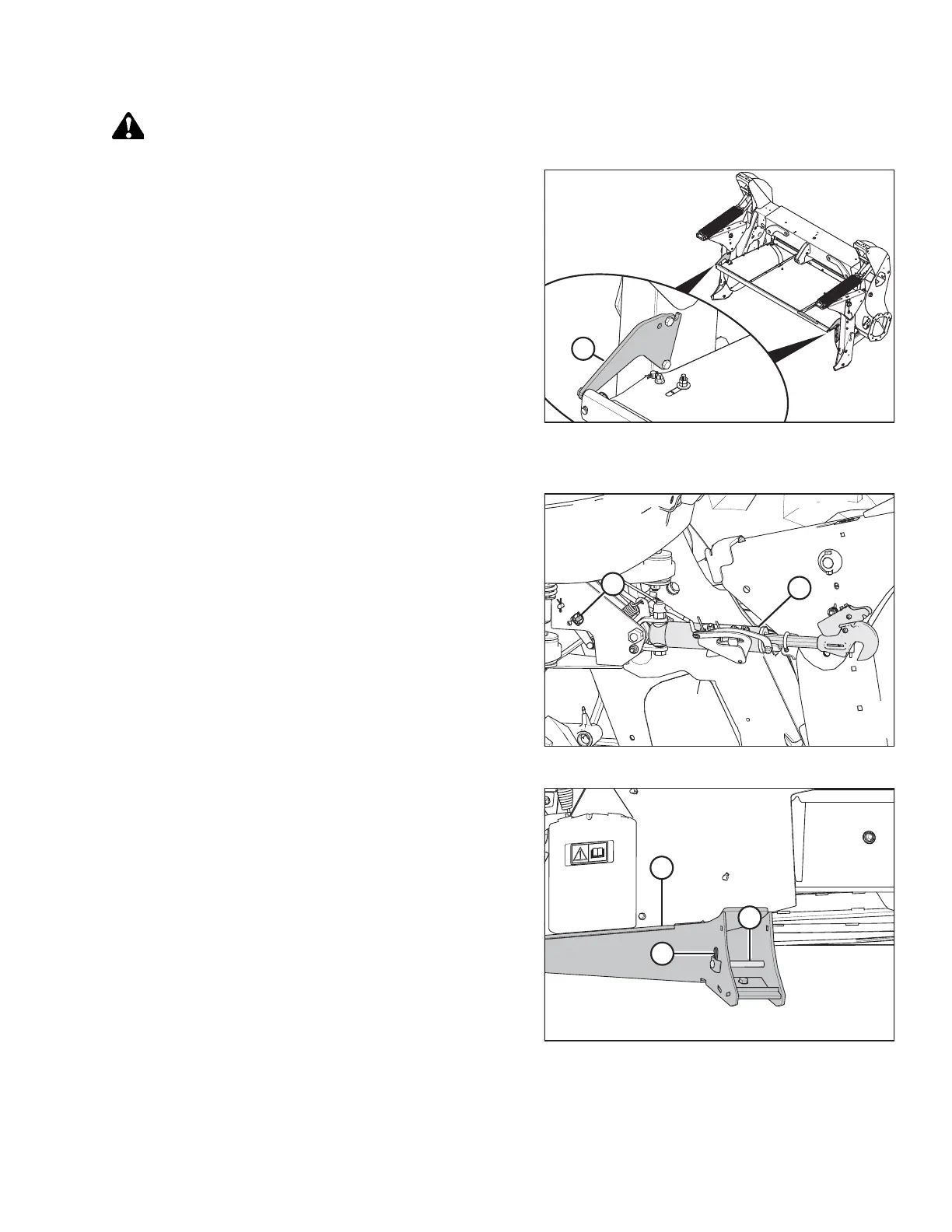
Figure 5.173: Shield Mount Plates on Forming Shield
IMPORTANT:
When attaching an R216 SP Rotary Disc Header to an M1 Series
Windrower that has been previously configured for a D1X Series
Draper Header, ensure the two shield mount plates (A)
(MD #307045) are attached to the windrower and forming shield.
1. Shut down the engine, and remove the key from the ignition.
Figure 5.174: Hydraulic Center-Link
2. Windrowers equipped with a hydraulic center-link without
self-alignment: Remove pin (A) and raise center-link (B)
until the hook is above the attachment pin on the header.
Replace pin (A) to hold the center-link in place.
IMPORTANT:
Ensure that the center-link is positioned high enough that it
does not contact the header as the windrower approaches
the header.
Figure 5.175: Header Support
3. Remove hairpin (A) from clevis pin (B), and remove the pin
from header support (C) on both sides of the header.
4. Start the engine.
ATTACHING A HEADER TO THE WINDROWER


 To Next Page