215620 60 Revision A
Float selector manifold hydraulic connections
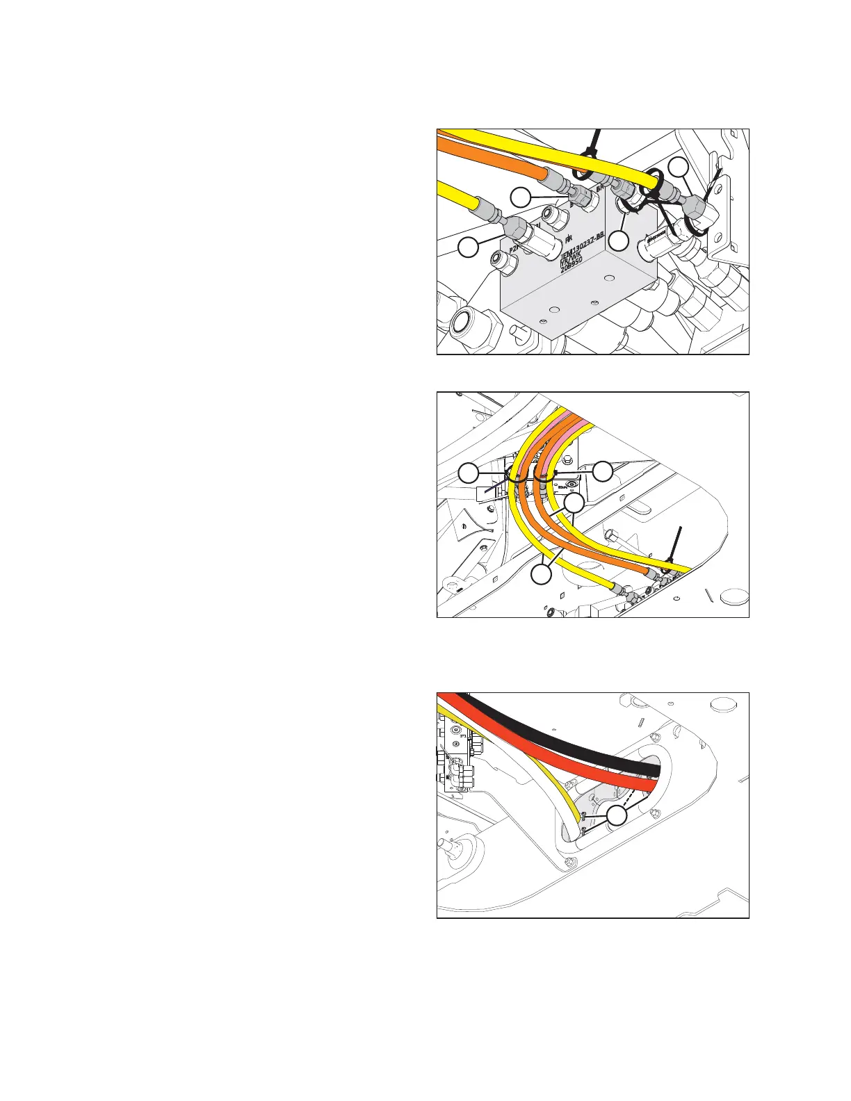
Figure 3.35: Float Selector Manifold
3. Connect hoses from the right wheel leg to the float selector
manifold as follows:
a. Connect the 1/4 in. ID brake hose (A) with no cable tie
to port BR.
b. Connect the 1/4 in. ID float hose (B) with no cable tie
to port FR with extension.
4. Connect hoses from the left wheel leg to the float selector
manifold as follows:
a. Connect the 1/4 in. ID brake hose (C) marked with a
black cable tie to port BL.
b. Connect the 1/4 in. ID float hose (D) marked with a
black cable tie to port FL with extension.
Figure 3.36: Securing Hoses
5. Use provided cable tie (A) to secure two hoses (B) (routed
from the right leg to the float selector manifold) to the case
drain hose marked with a blue cable tie.
6. Use provided cable tie (C) to secure two hoses (D) (routed
from the left leg to the float selector manifold) to the case
drain hose marked with a red cable tie.
Traction drive pump hydraulic connections
Figure 3.37: Hose Support at Cross Member
7. Route the traction drive hoses through the supports inside
the cross member and secure with cable ties (A).
ASSEMBLING WINDROWER