215620 62 Revision A
Electrical Connections
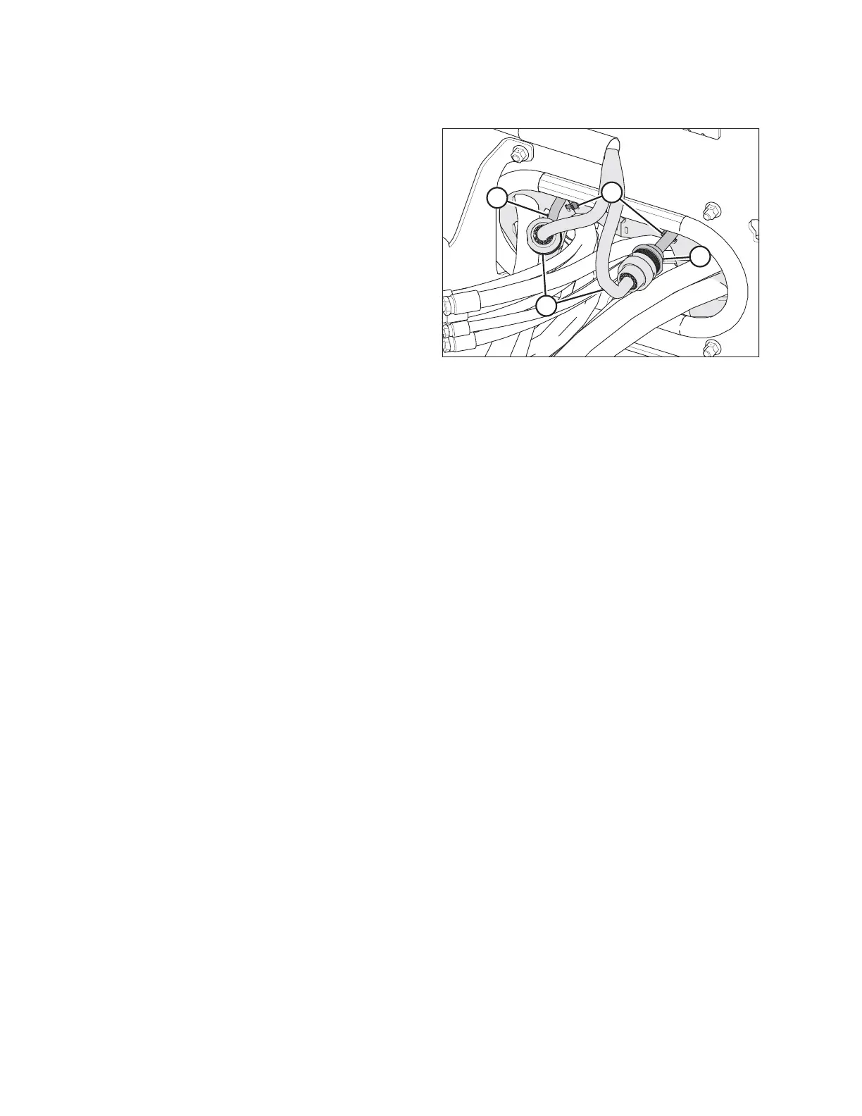
Figure 3.40: Electrical Connections
11. Route harness (A) from each wheel motor through the hose
support behind the front cross member, and connect it to
master controller harness (B) as follows:
• Connect the right wheel motor connector C25B to
master controller connector C25A.
• Connect the left wheel motor connector C26B to master
controller connector C26A.
• Secure the harness in the hose support with cable
ties (C).
ASSEMBLING WINDROWER