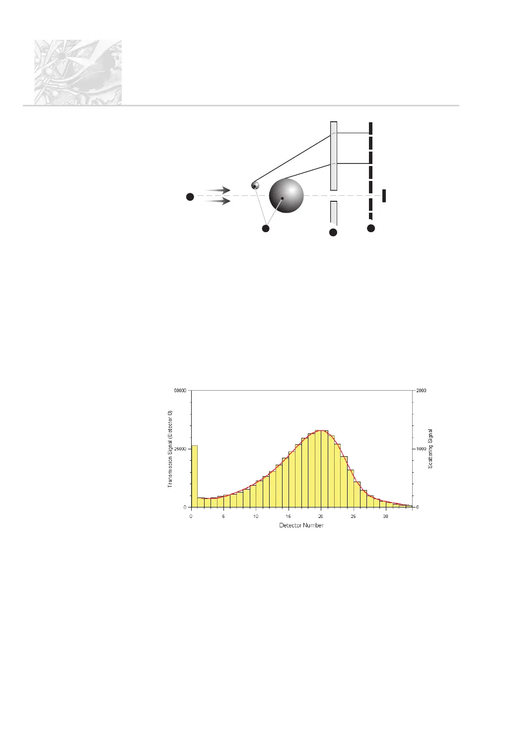
This diagram shows a parallel light source
+
, particles of different sizes
,
,
the focussing lens
-
and the detector array
.
.
.
There is also one extinction detector.
.
Diffraction is also influenced by the material which makes up the particles.
To take account of this, the user can supply information on the optical
properties (refractive index and density). For details see Chapter 10.
.
The scattering pattern from the spray is captured. This is known as the
“measurement”. The capture is controlled by the user, either manually or
using an SOP.
.
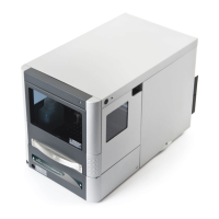
A typical light scattering pattern is shown below. Each bar in the histogram
represents the scattered light captured by one of the detectors (channels):
The detector array takes a snapshot of the scattering pattern. Note the following:
.
The pattern is a snapshot in time which relates directly to the size of the
particles.
.
The Spraytec can take snaps at a rate of 10kHz.
.
Continuous acquisition allows a history of the spray event to be built up.
CHAPTER 2
Spraytec
Page 2.4 MAN 0368
1
2
3
4
ILL 7427