TRANSMISSION AND TORQUE CONVERTER CD3340B/YB4411
7-52
Published 04/07/2015 Control # 569-00
14. Remove and discard piston and shaft O-rings (20 and
21).
15. To disassemble the opposite clutch, carefully remove
piston ring seals (22).
16. Loosen clutch end bearing (23) by tapping the assembly
on a piece of wood. Then remove the bearing using a
puller.
17. Remove needle roller thrust bearing (25) and thrust
washers (24).
18. Remove the gear and splined hub assembly (26) along
with needle roller bearing (6).
19. Repeat steps 5 to 14.
Assembly
Visually inspect the friction and counter plates:
• Counter plates
- light scoring/polishing is permissible,
plates that are flat, worn or heavily marked or scored
must be replaced with a new set.
• Friction Plates
- the cross hatching should be clearly
visible, plates that are flat, have friction material damage
or scoring must be replaced with a new set.
DO NOT mix old and new plates. If a plate is damaged/worn
install a complete new set.
Needle roller thrust bearings should slide into position freely,
do not bend or distort the cage to install. If the cage has been
distorted, install new bearings.
Take care when handling disc spring assemblies (14,
Figure 7-67) to avoid marking or damage, which could result
in stress cracking. If in doubt install a new disc spring.
1. Install new O-rings (20 and 21), lubricate with oil then
press piston (19) fully into bore of clutch housing.
2. Install oil baffle (18), piston spring (17). Make sure the
spring seats in the piston.
3. Install spring retaining plate (16).
4. Compress spring and secure with retaining ring (15).
5. Install disc spring assembly (14). Make sure that the disc
spring is installed with the teeth towards the clutch pack.
Make sure the teeth are not aligned with the lubrication
slots in the housing.
6. Install one counter plate (13), then install one friction
plate (12) followed by another counter plate. Continue
alternating friction and counter plates. Finish with a
friction plate.
7. Install pressure end plate (10). Make sure teeth are not
aligned with the lubrication slots in the housing. Do not
install shim (11) at this stage.
8. Install the clutch friction/counter plates retaining ring (9).
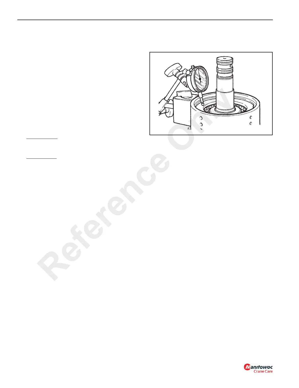
9. Using a dial test indicator as shown in Figure 7-73,
measure the end play of the pressure end plate. End
play should be 1.90 to 2.50 mm (0.075 - 0.098 in).
To adjust the end play, there is a choice between a 6.0
mm (0.23 in) or a 6.5 mm (0.25 in) pressure end plate
(11) with either a shim (10) or extra counter plate (13)
between retaining ring (9) and pressure end plate (11).
10. Install thrust washers (8) and needle roller thrust bearing
(7).
11. Install gear and spline hub assembly (5).
NOTE: Prior to installing the gear, align teeth of clutch
using a thin rod (screwdriver).
12. Install needle roller bearing (6).
13. Install needle roller thrust bearing (4) and thrust washer
(4A).
14. Coat the clutch end bearing (2) with a Lithium Base, E.P.
No. 2 bearing grease and press gear (3) and bearing (2)
onto the shaft.
15. Install piston ring seal (1). See (PTFE) Piston Ring Seal
Installation Procedure, page 7-58.
16. Repeat steps 1 to 10 for the opposite clutch.
17. Install gear and spined hub assembly (26) onto the shaft.
NOTE: Prior to installing the gear, align teeth of clutch
using a thin rod (screwdriver).
18. Install needle roller bearing (6).
19. Install needle roller thrust bearing (25) and thrust washer
(24).
20. Coat the clutch end bearing (23) with a Lithium Base,
E.P. No. 2 bearing grease and press the bearing onto
the shaft.
21. Install piston ring seals (22). See (PTFE) Piston Ring
Seal Installation Procedure, page 7-58.
Reference Only
 Loading...


