GROVE 7-51
CD3340B/YB4411 TRANSMISSION AND TORQUE CONVERTER
Published 04/07/2015 Control # 569-00
Disassembly
The following instructions are for repair of both the input and
forward clutch assemblies.
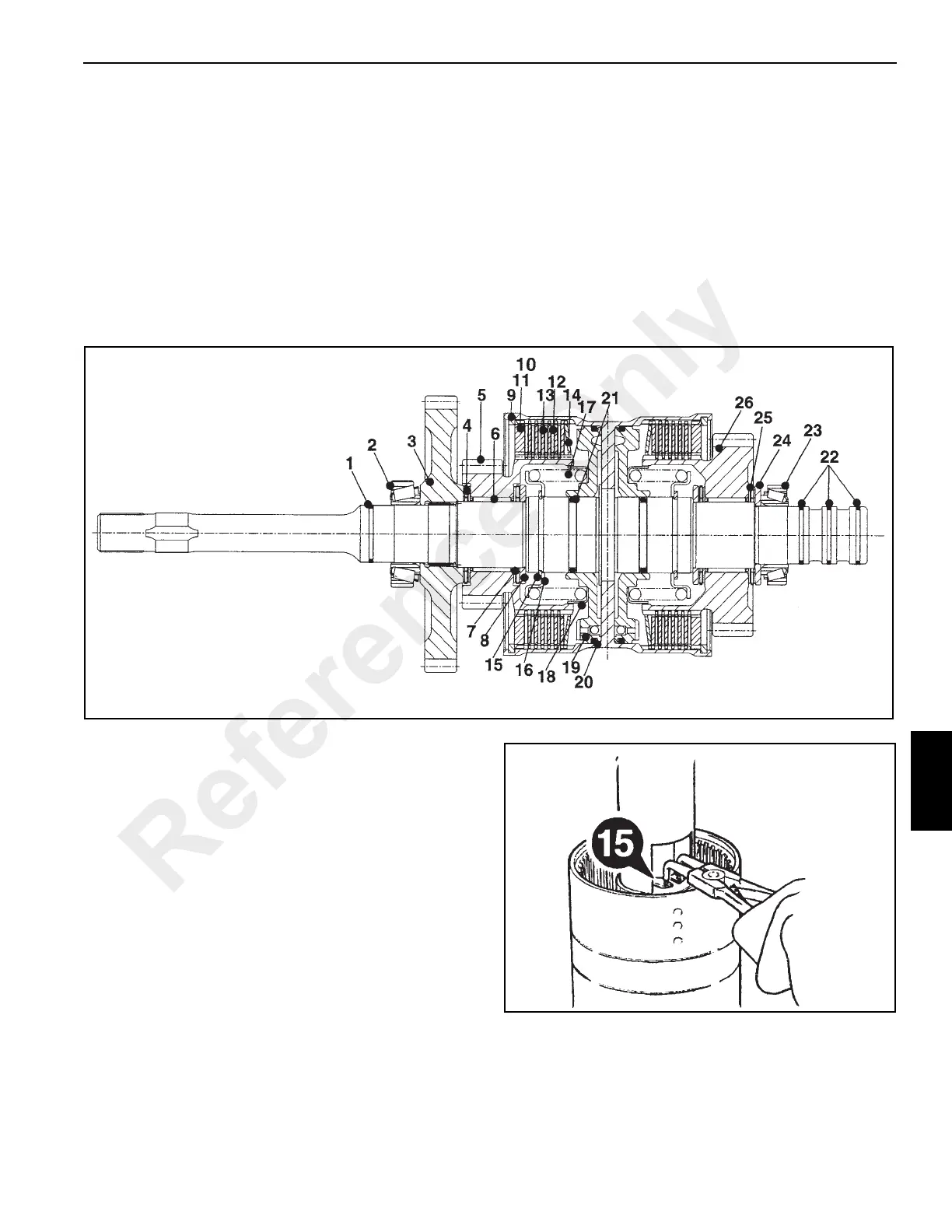
NOTE: Use both Figure 7-70 and Figure 7-71 for
reference. Item numbers are the same in both
illustrations.
1. Carefully remove piston ring seal (1).
NOTE: If the piston ring seals are excessively worn, then
check for burrs or damage on the shaft grooves. If
necessary, remove the burrs with a fine grade
abrasive paper and oil.
2. Remove the clutch end bearing (2) and gear (3), using a
collet tool and press.
3. Remove the needle roller thrust bearing (4) and thrust
washer (4A).
4. Remove the gear and splined hub assembly (5) along
with needle roller bearing (6).
5. Remove needle roller thrust bearing (7) and thrust
washers (8).
6. Remove friction/counter plates retaining ring (9).
7. Remove pressure end plate (11) and shim (10).
8. Remove friction plates (12) and counter plates (13).
Keep them together in sets. DO NOT mix the plates with
those of other clutches.
9. Remove disc spring assembly (14).
10. Position the clutch assembly in a press along with a
cutaway tube (Figure 7-72). Compress piston spring and
then remove retaining ring (15).
11. Lift off spring retaining plate (16).
12. Remove spring (17) and oil baffle (18).
13. Knock the clutch shaft on piece of aluminum (or wood) to
remove piston (19).
NOTE: If the piston does not loosen when the shaft is
knocked on aluminum, then hand pump air down
the shaft oil inlet hole.
Reference Only
 Loading...


