TRANSMISSION AND TORQUE CONVERTER CD3340B/YB4411
7-54
Published 04/07/2015 Control # 569-00
Disassembly
1. Carefully remove piston ring seals (1, Figure 7-74).
NOTE: If the piston ring seals are excessively worn, then
check for burrs or damage on the shaft grooves. If
necessary, remove the burrs with a fine grade
abrasive paper and oil.
2. Remove taper roller bearing (2) using a collet tool and
press.
NOTE: The bearing normally would not be removed unless
it was damaged. If a collet tool is not available, it is
permissible to use a standard bearing puller,
although damage to the bearing cage may occur
which will require a new bearing.
3. At the opposite end, loosen the clutch end bearing (3) by
tapping the assembly on a piece of wood. Remove end
bearing using a puller.
4. Remove friction/counter plates retaining ring (4).
5. Remove pressure end plate (5) and shim (6), if installed.
6. Remove clutch friction plates (7) and counter plates (8).
Keep them together as a set. DO NOT mix the plates
with those of other clutches.
7. Position the clutch assembly in a press along with a
cutaway tube (Figure 7-75). Compress the spring and
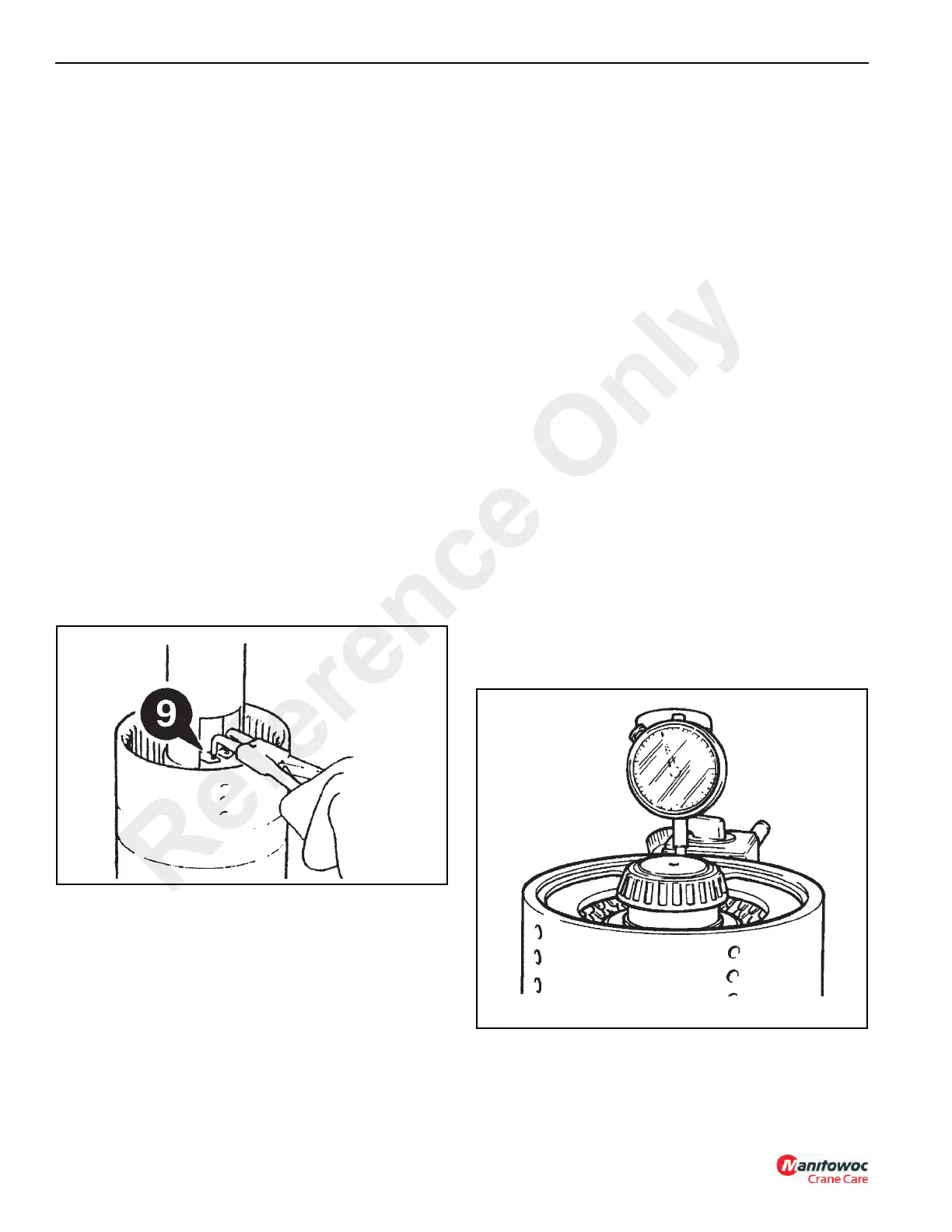
remove retaining ring (9).
8. Lift off spring retaining plate (10).
9. Remove spring (11) and oil baffle (12).
10. Knock the clutch on a piece of aluminum (or wood) to
remove piston (13).
NOTE: If the piston does not loosen when the shaft is
knocked on aluminum, then hand pump air down
the shaft oil inlet hole.
11. Remove and discard piston and shaft O-rings (14 and
15).
Assembly
Visually inspect the friction and counter plates:
• Counter plates - light scoring/polishing is permissible,
plates that are flat, worn or heavily marked or scored
must be replaced with a new set.
• Friction Plates - the cross hatching should be clearly
visible, plates that are flat, have friction material damage
or scoring must be replaced with a new set.
DO NOT mix old and new plates. If a plate is damaged/worn
install a complete new set.
Needle roller bearings should slide into position freely, do not
bend or distort the cage to install. If the cage has been
distorted, install new bearings.
1. Install new O-rings (15 and 14). Lubricate with oil and
then press piston (13) fully into bore of hub. Install
pressure end plate (5). Do not install shim (6) at this
stage. Make sure the teeth are not aligned with the
lubrication slots in the housing.
NOTE: A spring disc is not installed in this clutch pack.
2. Install the clutch friction/counter plates retaining ring (4).
3. Using a dial test indicator as shown in Figure 7-76,
measure the end play of the pressure end plate. End
play should be 0.075 - 0.098 inches (1.9 - 2.5 mm).
To adjust the end play, there is a choice between a 0.23
inch (6.00 mm) or a 0.25 inch (6.5 mm) pressure end
plate (5) with either a shim (6) or extra counter plate (8)
between retaining ring (9) and pressure end plate (5).
4. Coat the clutch end bearings (3 and 2) with a Lithium
Base, E.P. No. 2 bearing grease and press the bearings
onto the shaft.
5. Install piston ring seal (1). See (PTFE) Piston Ring Seal
Installation Procedure, page 7-58.
Reference Only
 Loading...


