GROVE 8-27
CD3340B/YB4411 AXLES/DRIVE SHAFTS/WHEELS AND TIRES
Published 04/07/2015 Control # 569-00
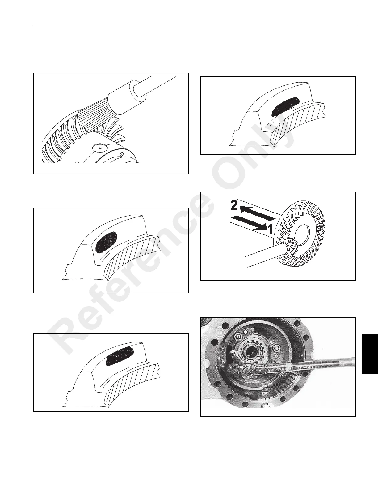
14. To test the tooth contact of the pinion with the bevel gear,
paint the teeth of the bevel gear with red lead paint
(Figure 8-106). The test should always be performed on
both sides of the bevel gear teeth.
15. Correct Contact. (Figure 8-107)
The bevel gear is adjusted correctly, the mark on the
pinion teeth will be regular.
16. Excessive contact on the tooth tip - Z contact.
(Figure 8-108)
Move the bevel gear away from the pinion to adjust the
backlash. See Figure 8-110.
17. Excessive contact at the tooth base - X contact.
(Figure 8-109)
Move the bevel gear toward the pinion to adjust the
backlash. See Figure 8-110.
18. Movements to correct backlash (Figure 8-110):
1. Move the bevel gear for type X contact adjustment.
2. Move the bevel gear for type Z contact adjustment.
19. Install the ring nut retainer turning the ring nut slightly to
align it with the retainer (Figure 8-111). Install the ring
nut retainer screw and tighten to a torque of 13 Nm (9.5
lb-ft).
Reference Only

 Loading...


