AXLES/DRIVE SHAFTS/WHEELS AND TIRES CD3340B/YB4411
8-28
Published 04/07/2015 Control # 569-00
Axle Beam and Brake Assembly
1. Inspect the friction disc and counterdiscs for signs of
burning. If burning is found, replace the discs. Also,
check the discs for wear. Replace any disc that is out of
tolerance.
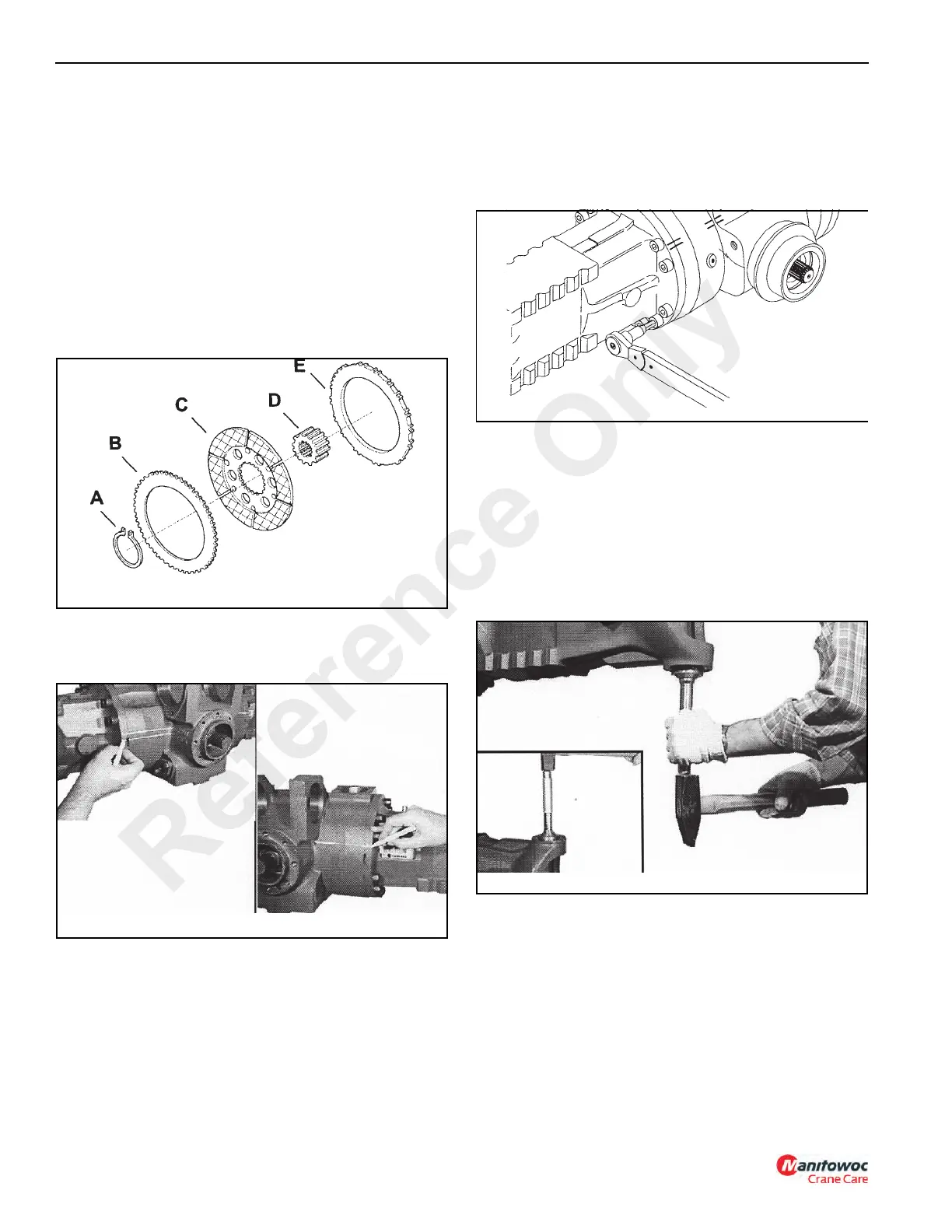
Assemble the components of the brake assembly inside
the brake flange in the sequence shown in Figure 8-112:
counterdisc (E), coupling (D) with the retainer ring
groove outward, friction disc (C), retaining ring (A) and
counterdisc (B).
NOTE: If new brake discs are being used, dip them in
Mobil Fluid 424 hydraulic oil before assembling.
2. To ensure correct assembly of the axle beams, check
the reference marks (Figure 8-113) made during
disassembly.
NOTE: Be sure to properly support the axle beams and
center housing during this assembly procedure.
3. Install a new O-ring into the axle beam housing. Install
the axle beam on the brake flange (Figure 8-114). Be
careful to align the mounting holes.
Install the mounting bolts and tighten to a torque of 320
Nm (235 lb-ft).
Axle Beam Group Assembly
1. Install the upper king bushing on the axle beam with
SPECIAL TOOL P/N 1901780 and a hammer
(Figure 8-115).
Install the cup of the ball bearing on the lower part of the
axle beam with SPECIAL TOOL P/N 1901780 and a
hammer.
NOTE: To make the installation easier, cool the bearing.
2. Install the bushing in the axle beam housing with
SPECIAL TOOL P/N 1901777 and a hammer
(Figure 8-116).
Fill 3/4 of the seal ring cavity with grease and apply a
sealing compound on seal ring’s outer surface.
Install the seal ring in the axle beam with SPECIAL
TOOL P/N 1901765 and a hammer.
Reference Only

 Loading...


