STEERING SYSTEM CD3340B/YB4411
10-14
Published 04/07/2015 Control # 569-00
14. Remove seal (4, Figure 10-9) from housing (8).
15. Remove set screw (25).
16. Screw a No. 10-24 machine screw into the end of check
ball seat (23). Then by pulling on the screw with a pliers,
lift the seat out of the housing.
17. Remove two seals (22 and 24) from the check ball seat.
18. Tip the housing to remove check ball (21) and check ball
retainer (20).
Inspection
Check all mating surfaces. Replace any parts that have
scratches or burrs that could cause leakage or binding.
Clean all metal parts in a clean solvent. Blow dry with air. Do
not wipe dry with a cloth or paper towel, because lint or other
matter can get into the hydraulic system and cause damage.
Do not use a coarse grit emory cloth or try to file or grind any
parts.
Replace all seals when assembling the unit. Lubricate all
seals with clean petroleum jelly before assembling. DO NOT
use excessive lubricant on seals for the meter section.
Assembly
1. Use a needle nose pliers to lower check ball retainer (20,
Figure 10-9) into the check valve hole in housing (8).
2. Install check ball (21) into housing (8).
3. Lubricate seals (22 and 24) and install them on check
ball seat (23).
4. Lubricate the check ball seat and seals thoroughly
before installing into the housing. When installing the
seat do not twist or damage the seals. Install the check
ball seat into housing, insert open end first. Push the
check ball seat to the shoulder of the hole.
5. Install set screw (25) and tighten to a torque of 11.3 Nm
(100 lb-in). To prevent interference, make sure the top of
the set screw is slightly below the housing mounting
surface.
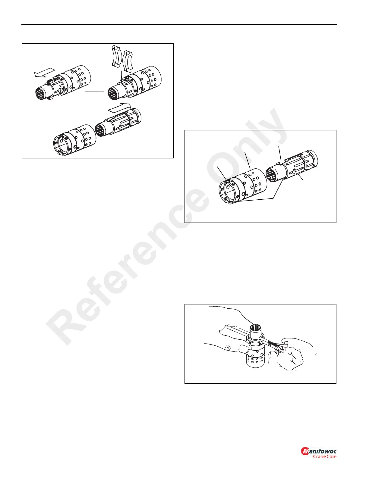
6. Lubricate the spool (12) and sleeve (9). Install spool (12)
and sleeve (9) carefully so that the spring slots
(Figure 10-15) line up at the same end. Rotate spool
(12, Figure 10-9) while sliding the parts together. Some
spools and sleeve sets have identification marks, align
these marks as shown in Figure 10-15. Test for free
rotation. The spool should rotate smoothly in the sleeve
with finger tip force applied at splined end.
7. Bring spring slots of both parts in line and stand parts on
end on the work bench (Figure 10-16). Insert special
spring installation tool through the spring slots of both
parts.
Position centering springs (in 2 sets of 3 each) on bench
so that the extended edge is down and arched center
section is together. In this position, insert one end of the
entire spring set (all six) into the spring installation tool,
as shown in Figure 10-16, with spring notches facing the
sleeve.
8. Compress the extended end of the centering spring set
and push into the spool and sleeve assembly,
withdrawing the installation tool at the same time.
9. Center the spring set in the parts so they push down
evenly and flush with the outer surface of the sleeve.
FIGURE 10-15
a0332
Spring
Slot
Control
Sleeve
Spring
Slot
Identification
Marks
Control
Spool
Reference Only

 Loading...


