GROVE 10-15
CD3340B/YB4411 STEERING SYSTEM
Published 04/07/2015 Control # 569-00
10. Insert pin (11, Figure 10-9) through the spool and sleeve
assembly until the pin becomes flush at both sides of the
sleeve.
11. Lubricate the spool and sleeve assembly and position
the assembly so that the splined end of the spool enters
the meter end of housing (8, Figure 10-9). See
Figure 10-17.
NOTE: Be extremely careful that the parts do not tilt out of
position while inserting. Push parts gently into
place with a slight rotation action; keep the pin
horizontal. Bring the spool assembly entirely within
the housing bore until the parts are flush at the
meter end of the housing. Do not pull the spool and
meter assembly beyond this point to prevent the
cross pin from dropping into the discharge groove
of the housing. With the spool assembly in this
flush position, check for free rotation within the
housing by turning with a light finger tip force at the
splined end.
12. Place the housing on a clean, lint free cloth. Install seal
(4, Figure 10-9) into housing (8).
13. Install needle bearing kit (6).
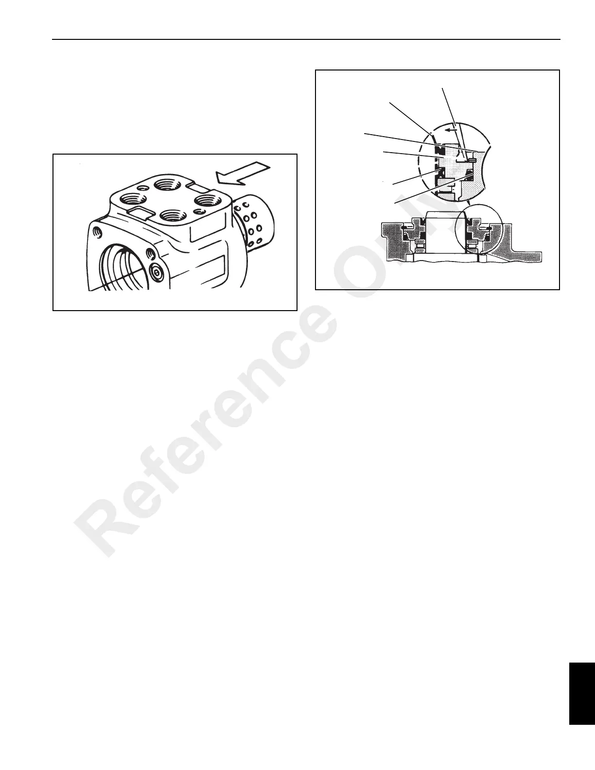
14. Install dust seal (1) into seal gland bushing (3). Flat or
smooth side of the dust seal must face down towards the
bushing. See Figure 10-18.
15. Install quad ring seal (5, Figure 10-9) into seal gland
bushing (3). Smooth seal in place with your finger. Do
not use any seal that falls freely into the pocket of the
bushing. See Figure 10-18.
16. Install seal gland bushing (3, Figure 10-9) over the spool
end with a twisting motion. Tap the bushing in place with
a rubber hammer. Make sure the bushing is flush
against the bearing race.
17. Install retaining ring (2, Figure 10-9) in the housing (see
Figure 10-18). After installing the retainer ring, tap on
ring end or pry with a screwdriver around entire
circumference of the ring to properly seat the ring in the
groove.
18. Clamp housing (8, Figure 10-9) in a vise. Clamp lightly
on edges of mounting area. Do not over tighten the vise
jaws.
NOTE: Check to ensure that the spool and sleeve
assembly are flush or slightly below the mounting
surface.
NOTE: Clean the upper surface of the housing by wiping
with the palm of your hand. Clean each of the flat
surfaces of the meter section parts in a similar way
when ready for assembly. DO NOT USE cloth or
paper to clean the surfaces.
19. Install seal (13) into grove in housing (8). Install spacer
plate (14). Align bolt holes in spacer plate with tapped
holes in the housing.
20. Rotate the spool and sleeve assembly until pin (11) is
parallel with the port face (see Figure 10-19). Install
drive (15, Figure 10-9), Make sure you engage the drive
with pin (11). To ensure proper alignment, mark the drive
as shown in Figure 10-20, Ref. B. Note relationship
FIGURE 10-18
a0337
Screwdriver
Dust Seal
Retaining Ring
Seal
Gland Bushing
Quad Ring Seal
Seal
Reference Only

 Loading...


