STEERING SYSTEM CD3340B/YB4411
10-16
Published 04/07/2015 Control # 569-00
between the slotted end of the drive to the splined end of
the drive when marking.
21. Install seal (13, Figure 10-9) into the gerotor (16).
22. With seal side of the gerotor toward spacer plate (14),
align star valleys (Figure 3-24, Ref. A) on drive (Ref. B).
Note the parallel relationship of reference lines A, B, C
and D. Align bolt holes without disengaging the gerotor
from the drive.
23. Install drive spacer (17, Figure 10-9) into the gerotor.
24. Install seal (13) into end cap (18). Install end cap (18)
onto gerotor (16). Align the bolt holes.
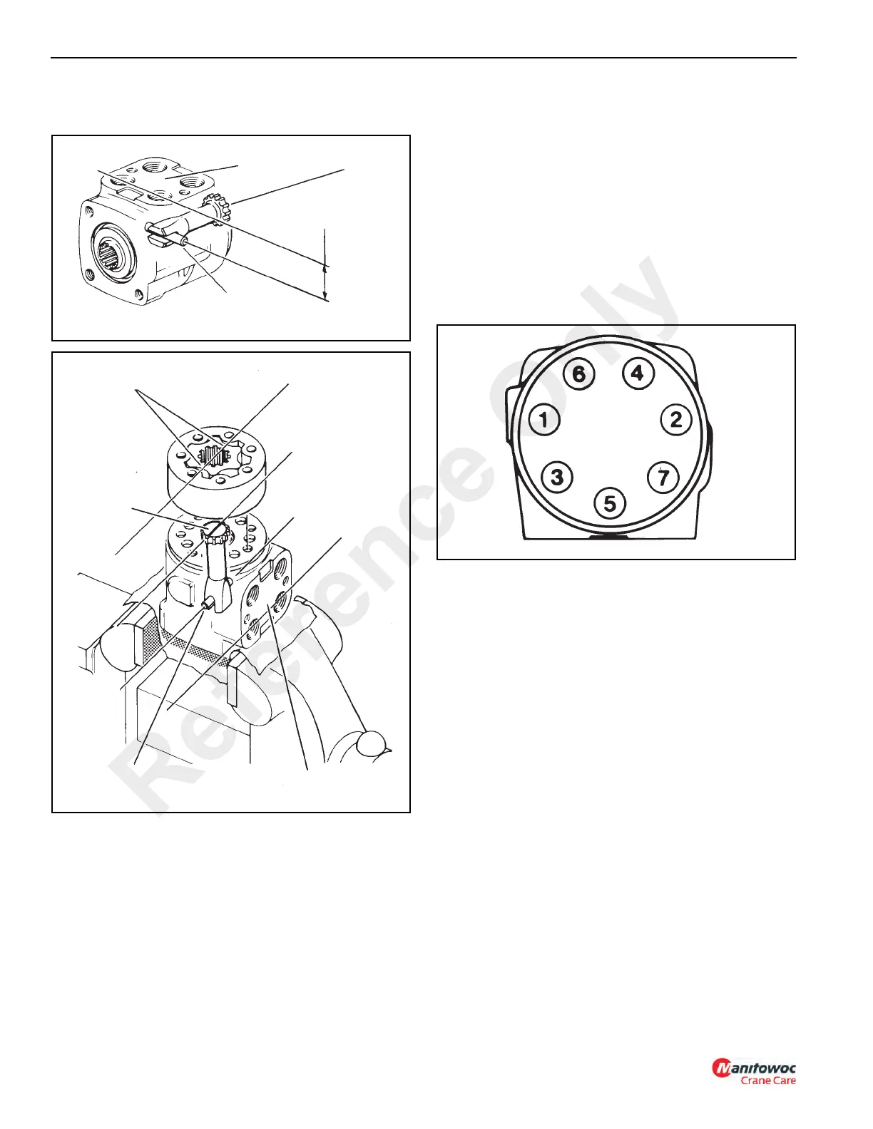
25. Install the seven 6 pt. Torx Drive screws with new seal
washers in the end cap. Tighten each screw to 150 lb-in,
then tighten each screw in sequence shown in
Figure 10-21 to a torque of 31 Nm (275 lb-in).
Installation
1. Locate the steering orbitrol and steering column in
position on the mounting bracket under the instrument
panel. Secure in place with four bolts and numerous flat
washers.
2. Connect the hydraulic lines to the steering orbitrol.
3. Check the hydraulic oil level in the reservoir. Fill if
necessary.
4. Start the engine and turn the steering wheel in both
directions to fill the lines with hydraulic fluid and bleed air
from the system. Check for leaks and repair if necessary.
5. Check the hydraulic oil level in the reservoir. Fill if
necessary.
6. Install the outside cover to the operator’s compartment.
FIGURE 10-19
a0336
Port Face
Drive
Pin Parallel with Port
Face
Pin
FIGURE 10-20
a0338
A
B
C
D
Port Face
Pin
Drive
(Marked)
Gerotor
Star Valley
Reference Only

 Loading...


