STRUCTURAL CD3340B/YB4411
11-14
Published 04/07/2015 Control # 569-00
15. Remove the socket and special pin. Install cotter pin (57)
in place of the pin.
16. Install lock wire (80) between cotter pins (57 and 58).
17. Turn jam nut (64) about 3/4 of the way onto threaded
chain end (63).
18. At the front of the 1st boom section install the threaded
chain end (63). Install nut (65).
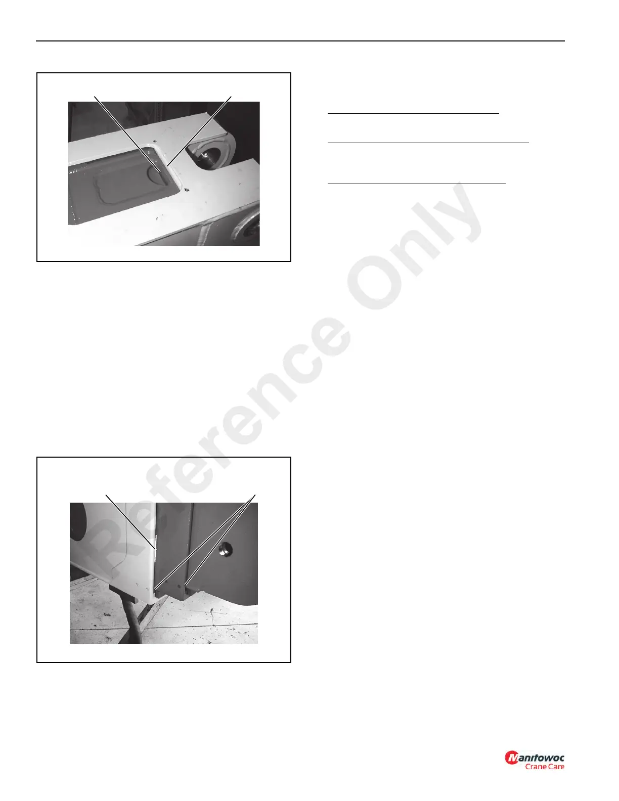
19. Place a pencil mark on the 2nd boom section where the
1st boom section overlaps the 2nd (Figure 11-22).
20. Tighten nut (65) until the pencil mark starts to move
away from the 1st boom section. Stop and tighten the
jam nut against the boom bracket. Make sure that the
chain is not twisted.
21. Install the hoses from the two telescope cylinder hoses
to the bulkhead in the 1st boom section.
22. At the front of the second boom section (Figure 11-22),
install brass wear pads (40) between the 2nd and 3rd
boom sections.
Wear Pad (Units prior to S/N 100710-99)
P/N 1004468 = 11.18 mm (0.44 in)
Wear Pads (Units with S/N 100710-99 and After
P/N 1005703 = 6.35 mm (0.25 in)
P/N 1005524 = 7.87 mm (0.31 in)
Shims Units with S/N 100710-99 and After
P/N 1005522 = 1.02mm (0.04 in)
P/N 1005475 = 1.78 mm (0.07 in)
Install the wear pads and, if required, the shims at four
places to center the 3rd boom assembly in the 2nd boom
assembly.
23. Repeat Step 22 and install the wear pads between the
1st and 2nd boom sections.
24. Locate the pivoting boom head between the 3rd section
ears. Install pin (6) and fasten with capscrew (8) and
lockwasher (7).
25. Install pin (4) and fasten with lynch pin (5).
26. Install any components that were removed from the 1st
boom section prior to disassembly, i.e. boom angle
indicator, cord reel.
Installation
1. Connect the anti-double block system wire to the boom
head wire.
NOTE: Use at least a 1.8 Metric Ton (2 ton) overhead
crane when lifting the boom assembly. Be sure
slings and/or chains are capable of handling 1.8
Metric Ton (2 ton).
2. Using a sling, or chains and overhead hoist, position the
boom assembly between the ears of the mast. Install the
mounting pin and fasten with a capscrew and
lockwasher.
3. Attach the lift cylinder to the boom assembly.
4. Connect the hoses from the hydraulic swivel to the
bulkhead fittings on the boom assembly.
5. Connect the anti-double block system electrical wire to
the electrical swivel or connect the rated capacity limiter
(RCL) electrical wire to the electrical swivel.
6. Install the wire rope over the boom head and reeve
through boom head and drop block sheaves and dead
end with wedge and socket. Connect the wedge socket
to the pivoting boom head.
FIGURE 11-21
p0680
3rd Boom Section Bottomed
Against 2nd Boom Section
2rd Boom Section Bottomed
Against 1st Boom Section
p0681
FIGURE 11-22
Upper Wear Pad Locations (Not Shown)
Pencil Mark
Install Wear Pad
(Both Sides, Upper
and Lower)
Reference Only

 Loading...


