GROVE 11-13
CD3340B/YB4411 STRUCTURAL
11
Published 04/07/2015 Control # 569-00
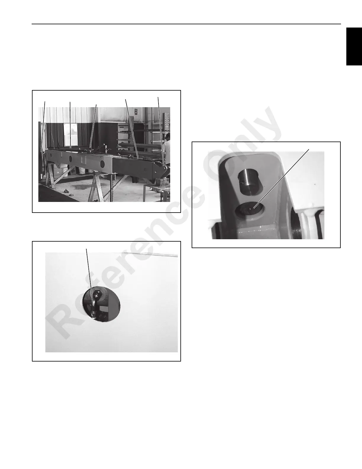
7. Slide the 2nd boom assembly into the 1st boom
assembly far enough that the telescope cylinder hoses
can be installed through the rear of the boom. If the 2nd
boom assembly will not slide into the 1st boom section it
is permissible to hook up a chain jack as shown in
Figure 11-18 and jack the boom sections into the 1st
boom section.
8. Install the two hoses to the telescope cylinder so they
are hanging straight down (Figure 11-19). It may be
necessary to rotate the cylinder to align the hose ports.
9. Pull the 2nd boom assembly into the 1st boom assembly
until the eccentrics are visible in the access hole.
10. Check that the threaded end of the telescope cylinder
aligns with and can be installed in the mounting hole in
the boom section (Figure 11-20). If it can not be
installed, it must be adjusted as follows:
a. Loosen the two eccentric mounting capscrews (32).
b. Using the special spanner turn the eccentrics until
the rod can be installed in the mounting hole. There
is a shoulder on the cylinder threaded rod that must
also clear the hole. Be sure that the telescope
cylinder assembly still is centered. Adjusting one
eccentric too much may pull the telescope assembly
to one side.
c. Tighten the two eccentric mounting capscrews.
11. Install the cylinder rod end through the mounting hole.
Install extend rod (24) through its mounting hole in the
boom section and pull the rod tight.
12. Install washer (60) and castle nut (59). Using a 3-1/8
inch socket, tighten the nut until the cylinder is tight
against the mounting plate. Then back off the nut until
one of the slots in the nut aligns with the cotter pin hole.
Install cotter pin (58).
13. Turn castle nut (56) onto extend rod (24) until the cotter
pin hole shows in one of the nut slots. Insert special pin
(Figure 11-8) into the cotter pin hole, while installing a
1-7/8” socket onto the nut. The socket will hold the pin in
the cotter pin hole.
14. Tighten the nut, which will turn extend rod (24) into the
chain end (23). Observe the 3rd boom section through
the top access hole (Figure 11-21). When it starts to
separate from the 2nd boom section, stop tightening the
nut.
FIGURE 11-18
p0677
Pin
Sling
Chain
Jack
Sling
Pin
FIGURE 11-19
p0678
Install Hose Straight Down
FIGURE 11-20
p0679
Align Rod with Hole
Reference Only

 Loading...


