STRUCTURAL CD3340B/YB4411
11-12
Published 04/07/2015 Control # 569-00
12. At the rear of the boom (Figure 11-15), check for proper
height adjustment. Using a tape measure and straight
edge, measure from the center of the telescope cylinder
threaded rod to the bottom of the slide pad on retract
roller assembly (37). It should be 187 mm (7.75 in). If it is
not correct, turn the two eccentrics, while maintaining
the centering of the telescope cylinder assembly, to
either raise or lower the cylinder rod to correct
measurement. When the dimension is correct, tighten
the two eccentric retaining bolts.
13. Check that the telescope cylinder assembly has
remained centered. If it is not, adjust it using the
eccentrics.
14. Remove retract roller assembly (37) that was
temporarily installed in Step 10.
Installing the 2nd Boom Section into the 1st Boom
Section
Refer to three-section boom assembly diagram at the end of
this manual for all part numbers in this section.
1. Coat the internal slide areas on the 1st boom section
with an anti-seize compound.
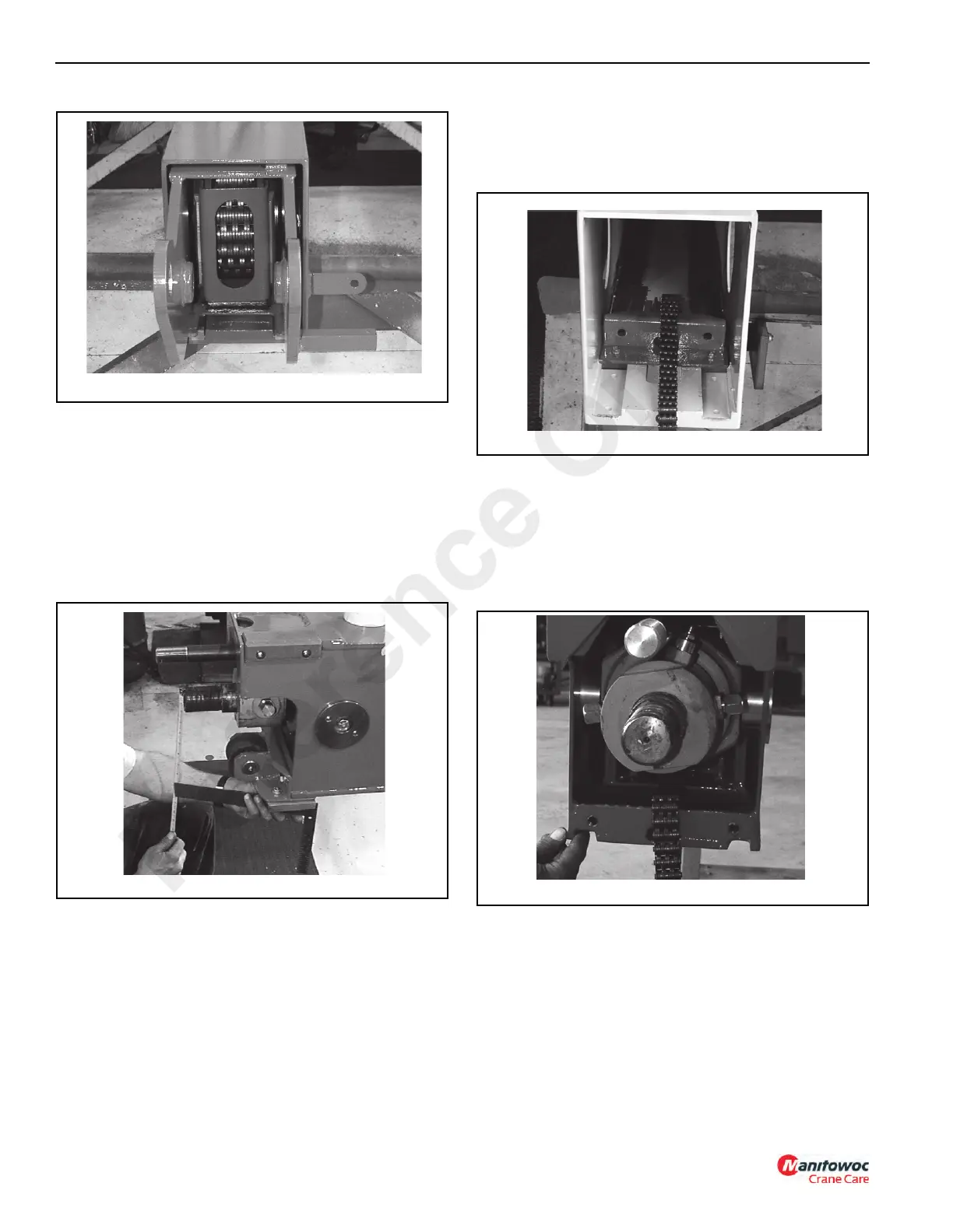
2. Position retract roller assembly (37) in the 1st boom
section. See Figure 11-16.
3. Place the lower retract chain (26, Figure 11-7) up
through bottom access hole and over the roller of the
retract roller assembly. See Figure 11-17.
4. Position the 2nd boom assembly in front of the 1st boom
assembly close enough to connect the lower retract
chain (26), (Figure 11-10) to the chain end (31) using pin
(28) and cotter pins (27). See Figure 11-17.
5. Insert the 2nd boom assembly into the 1st boom
assembly far enough to attach the retract roller chain
assembly to the 2nd boom assembly, through the first
access hole.
6. Coat the tops of the two lower slide pads (49) with an
anti-seize compound. Install the two lower slide pads
(49) with four capscrews (51) and lockwashers (50). Do
not over tighten the capscrews. It is possible to pull the
slide pad nuts through the slide pads.
Reference Only

 Loading...


