GROVE 11-11
CD3340B/YB4411 STRUCTURAL
11
Published 04/07/2015 Control # 569-00
the 3rd section upper slide pads will slide, with anti-seize
compound.
2. Using an overhead crane and sling, align the 3rd boom
section with the end of the 2nd boom section.
3. Insert the 3rd boom section into the 2nd boom section,
raising the boom tip end of the 3rd boom section slightly
to clear an internal plate. Then lower tip and continue
inserting the 3rd boom section until it is approximately
half way in.
4. Coat the tops of the two lower slide pads (43) with an
anti-seize compound. Install the two lower slide pads
(43) with four capscrews (45) and lockwashers (44). Do
not over tighten the capscrews. It is possible to pull the
slide pad nuts through the slide pads.
5. Continue inserting the 3rd boom section into the 2nd
boom section until it bottoms out.
6. Attach a sling and overhead crane to the threaded rod
end of the telescope cylinder (Figure 11-9).
7. Using a pry bar (Figure 11-12), pry the 3rd boom section
about 3.2 mm (1/8 in) away from the 2nd boom section.
8. Using the sling and overhead hoist, raise the 3rd boom
section enough to install rear slide pad (12). Install the
pad using two capscrews (14) and lockwashers (13).
Lower the 3rd boom section.
9. Coat the inside surface of both eccentrics (33) with an
anti-seize compound. Coat the threads of capscrew (32)
with Loctite 243. Install both eccentrics using capscrew
(32). Tighten capscrew (32) to seat the eccentric and
then loosen the capscrew.
10. Install retract roller assembly (37) to the 2nd boom
section using two capscrews (39). The assembly is
installed temporarily to perform a centering
measurement.
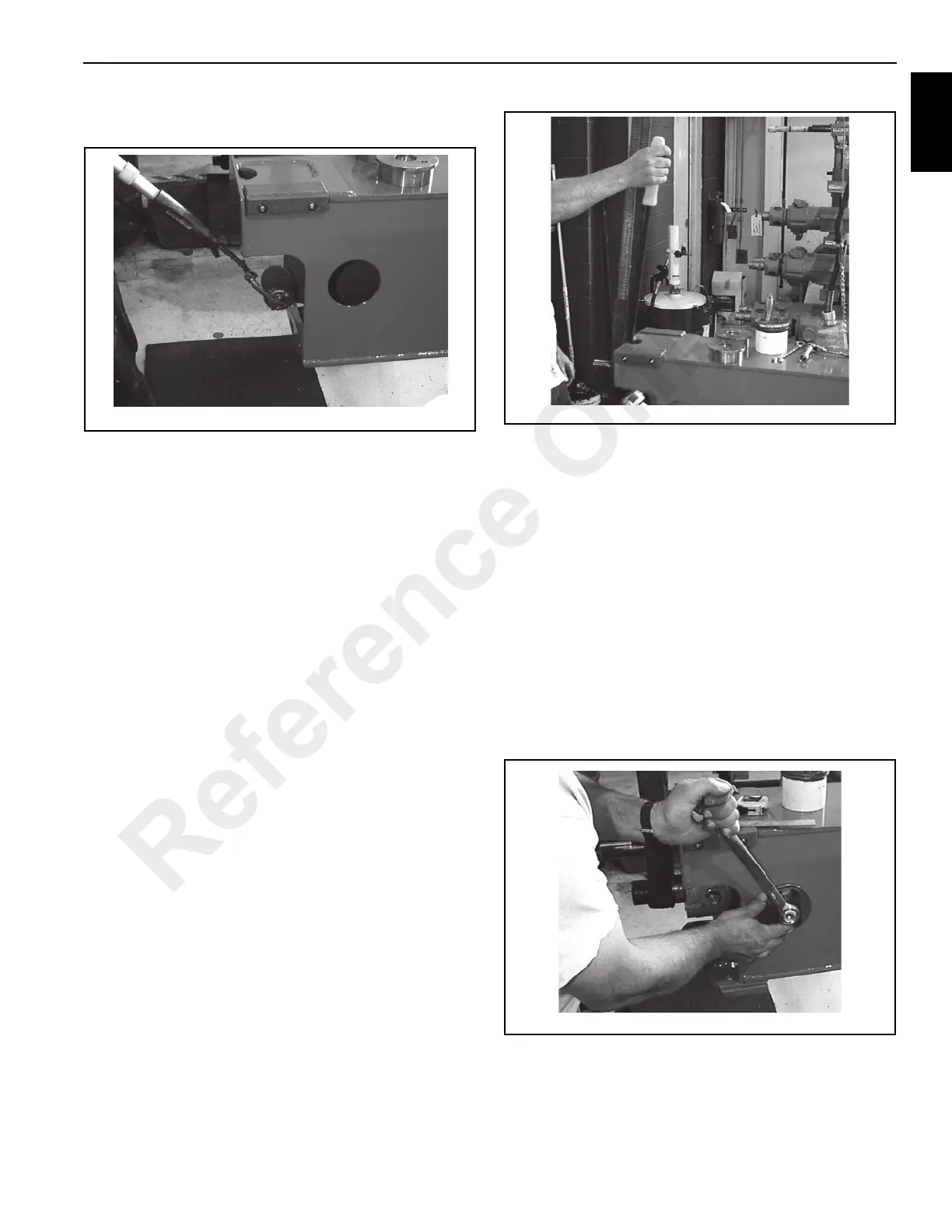
11. Using a spanner (see Special Tools), turn each eccentric
(Figure 11-13) until the telescope cylinder assembly is
centered in the 3rd boom section (Figure 11-14).
Reference Only

 Loading...


