GROVE 11-37
CD3340B/YB4411 STRUCTURAL
11
Published 04/07/2015 Control # 569-00
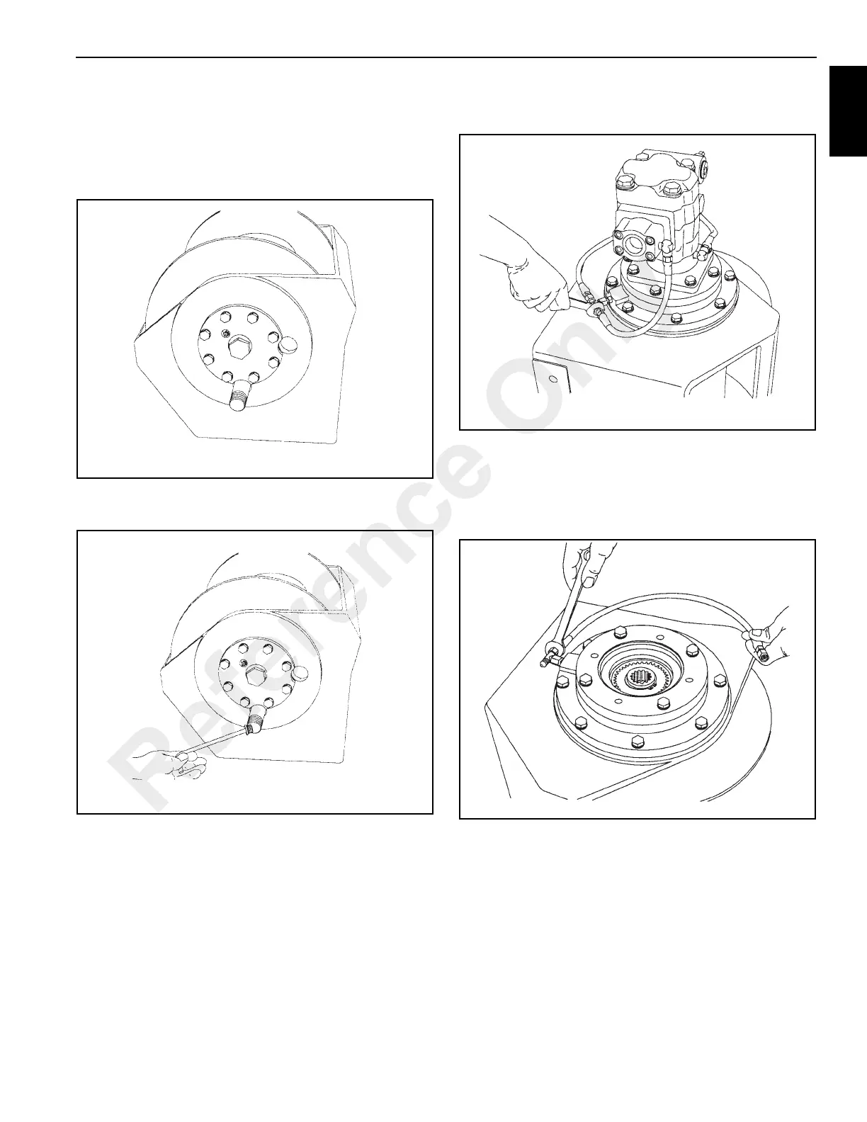
thoroughly clean the outside surfaces. To drain the oil,
install a short piece of 1 inch threaded pipe in the larger
threads of the drain hole (Figure 11-84). If necessary,
insert a bar in the wedge socket anchor pocket and
manually rotate the drum in the direction to hoist a load
until the drain holes align.
2. Use a 5/16 inch Allen wrench to remove the drain plug
through the pipe (Figure 11-75).
IMPORTANT!
It is not necessary to remove the hoist tension roller
subassembly to disassemble the hoist. But if it becomes
necessary, see page 11-57 for disassembly procedures.
3. Begin disassembly by removing the oil level plug and
standing the hoist on the bearing support end. Tag and
remove the hydraulic hoses that connect the brake valve
and manifold to the brake cylinder (Figure 11-76).
4. Remove the capscrews securing the motor, and lift the
motor off the hoist. Remove and discard the O-ring
installed on the pilot of the motor.
5. Tag and remove the hoses and fittings from the brake
cylinder release port (Figure 11-77).
6. Remove the brake clutch (Figure 11-78.) assembly from
the motor support. Refer to “Brake Clutch Service,”
page 11-49 for additional information.
Reference Only

 Loading...


