STRUCTURAL CD3340B/YB4411
11-38
Published 04/07/2015 Control # 569-00
7. Remove the motor support capscrews and install two (2)
capscrews and a short piece of chain (Figure 11-79) into
the motor mounting bolt holes. Using the chain as a
handle, lift the motor support out of the brake cylinder
being careful to avoid damaging the sealing surfaces.
Remove and discard the O-ring and backup ring from
the motor support. Refer to “Motor Support-Brake
Cylinder Service,” page 11-45 for additional information.
8. Remove the brake cylinder capscrews and install two (2)
capscrews and a short piece of chain into the motor
support mounting bolt holes. Using the chain as a
handle, lift the brake cylinder out of the drum and base,
being careful to avoid damaging the sealing or bearing
surfaces. Refer to “Motor Support-Brake Cylinder
Service,” page 11-45 for additional information.
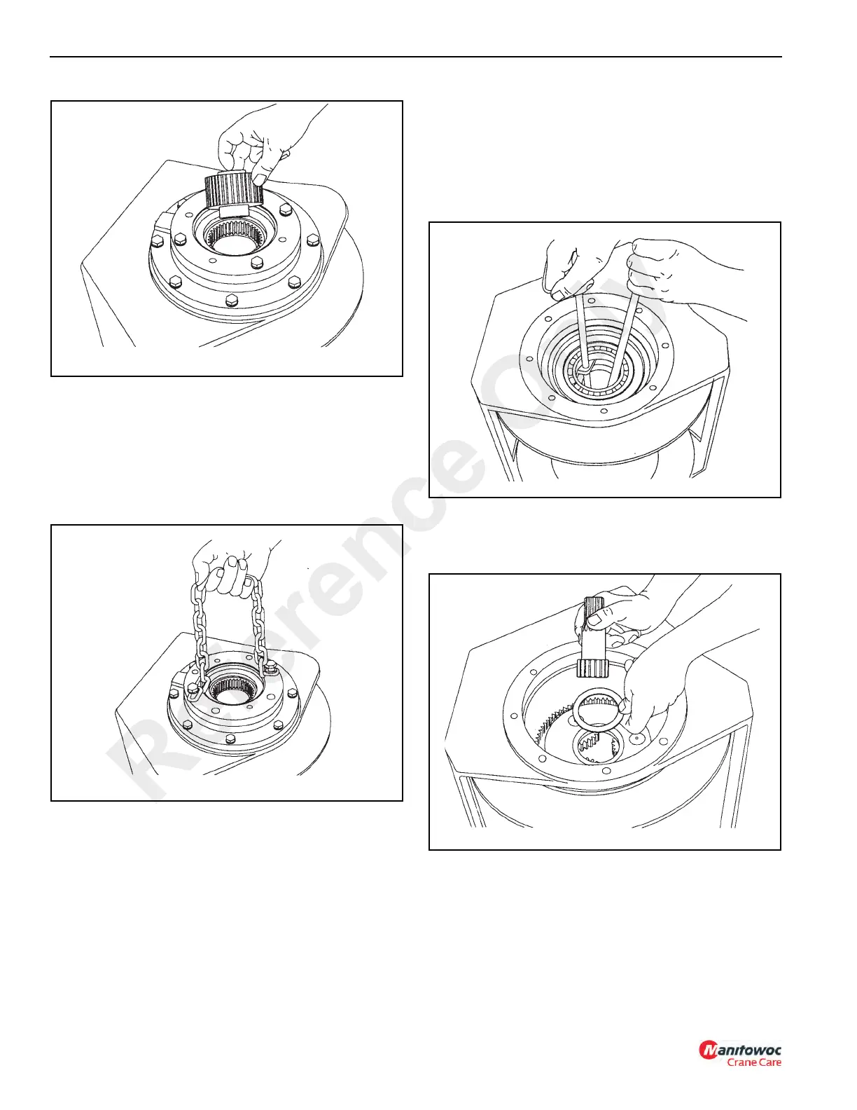
9. Using two heel type pry bars (Figure 11-80) placed
between the primary planet carrier and the drum
closure, pry upward to remove the drum closure.
Remove and discard the O-ring from the outside of the
drum closure.
10. Remove the seal and bearing from inside of closure.
11. Remove the primary sun gear and thrust washer
(Figure 11-81) from the primary planet carrier.
12. Remove the primary planet carrier from the drum
(Figure 11-82). Refer to “Planet Carrier Service,”
page 11-43 for additional information.
Reference Only

 Loading...


