STRUCTURAL CD3340B/YB4411
11-46
Published 04/07/2015 Control # 569-00
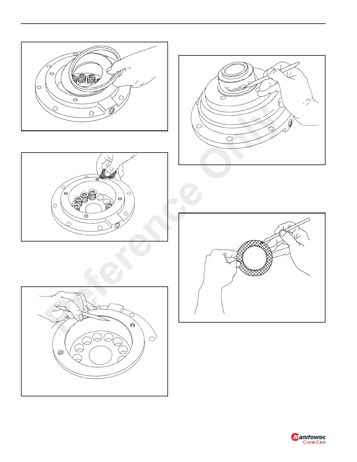
3. Remove brake springs (Figure 11-109) and the spring
spacer.
Clean and Inspect
1. Thoroughly clean and inspect all parts at this time.
Check brake piston sealing surfaces on the brake
cylinder and motor support. Be sure brake release port
is free of contamination (Figure 11-110).
2. Check oil seal and bearing surfaces on the brake
cylinder for damage and wear (Figure 11-111).
3. Place friction plate disc on a flat surface and check for
distortion with a straight edge. Friction material should
appear even across the entire surface with the groove
pattern visible. Replace the friction disc if the splines are
worn to a point, disc is distorted, friction material is worn
unevenly, or the groove pattern is worn away.
4. Place the steel brake disc on a flat surface and check for
distortion with a straight edge. Check surface for signs of
material transfer or heat. Replace the steel disc if the
splines are worn to a point, disc is distorted, or if it is heat
discolored.
5. Check the brake spring free length (Figure 11-113).
Minimum free length is 30.2 mm (1-3/16 in). Check
springs for any sign of cracking or failure. If a brake
spring must be replaced, then all brake springs must be
replaced.
Reference Only

 Loading...


