SETUP AND INSTALLATION MLC165-1 OPERATOR MANUAL
4-52
Published 08-06-19, Control # 237-09_v2
3. SLOWLY continue to boom up.
4. If equipped with an upper boom point, stop when the
bottom holes in the upper boom point are aligned with
the holes in the boom top. Install the connecting pins.
See Install the Upper Boom Point on page 4-100
.
5. Continue to raise the boom until the lower and upper
boom points are at a convenient height for installing the
load block(s) and hook-or-weight ball.
6. Install the load block(s) and hook-or-weight ball at the
lower and upper boom points. See Install the Boom
Load Lines on page 4-102.
7. Install the block-up limit components at the boom points.
See Install the Boom Block-Up Limit Components on
page 4-102.
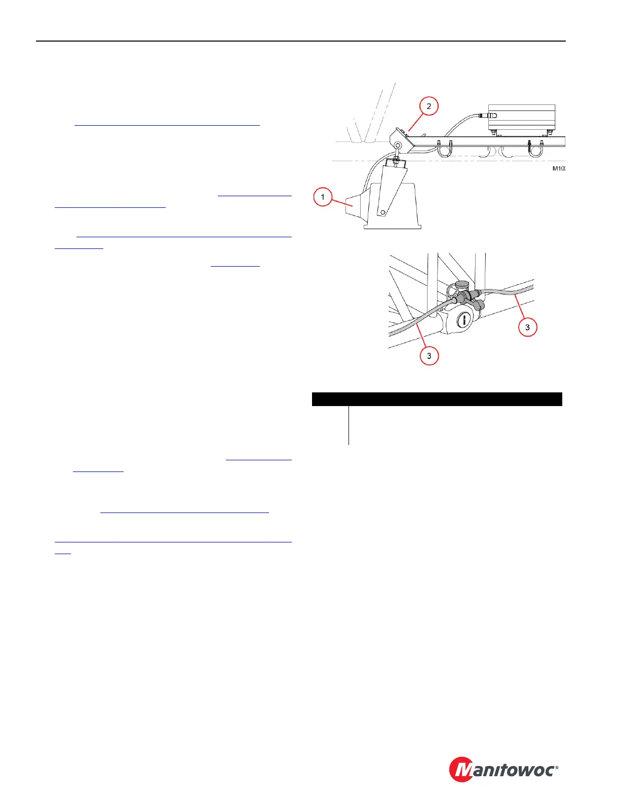
8. If equipped with optional work lights (Figure 4-43
):
a. Install the light fixtures (1) under the boom sections
once the boom can be raised to horizontal. See the
Boom Light Fixture Drawing at the end of this
section.
b. Connect the electric cables (3) between the boom
sections.
9. If equipped with a jib, continue to raise the boom until the
jib point is at a convenient height to install the load block
or the hook-or-weight ball.
a. Signal the operator to STOP raising the boom if the
jib pendants get caught on the brackets, pins, or
timber guards. Correct the problem before
continuing.
b. Make sure the jib stop pins (5, Figure 4-87 on
page 4-113) fully engage the holes in the jib stop
frame.
10. Install the load block or hook-or-weight ball at the jib
point. See Install the Jib Load Lines on page 4-115
.
11. Install the block-up limit components at the jib point. See
Install the Jib Block-Up Limit Components on page 4-
115.
12. Continue to boom up until the boom is at an angle that
safely allows the load block(s) and hook-and-weight ball
to be lifted.
13. Once the boom is raised:
a. Check all crane functions for proper operation.
b. Check all safety devices for proper operation (see
Section 3 of the MLC165-1 Operator Manual).
c. Check that the boom stop is adjusted for the proper
maximum boom angle.
d. Check that the RCL/RCI is properly calibrated.
Figure 4-43
Item Description
1Light Fixture
2 Cap Screws with Lock Nuts
3 Electric Cables