Adjusting the Print Heads Replacing and Adjusting the Print Heads
9-6 Sprinter User's Manual
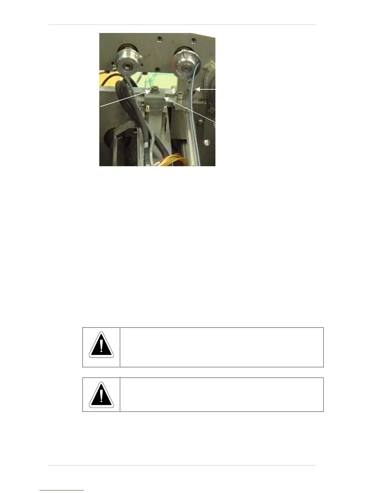
Figure 9-: The Print Head Locking Plate
Print Head Adjustment
The software allows jumps of one bit (0.0635mm).
You can obtain more accurate adjustment of the P
RINT HEADS by turning
the A
DJUSTMENT SCREW.
Each turn of the A
DJUSTMENT SCREW results in a movement of eight bits
(which is approximately 0.5mm).
To obtain the maximum accuracy, recheck the output of the "linen" file
with a magnifying glass, to see if all four lines are aligned one on top of the
other—both on the X and Y-axis.
There is one main direction in which the P
RINT HEAD can be moved in order
to achieve optimal results – with or against the printing direction i.e.,
forwards or backwards.
To adjust the P
RINT HEADS so that they are in their exact required location,
each head should be adjusted separately and independently.
• Before moving the heads:
• Make sure that the pistons are down.
• Loosen the T
IGHTENING SCREWS that
secure the L
OCKING PLATE.
Turn the Adjustment Screws clockwise to move backward, and anti-
clockwise to move forward.
To adjust a Print Head to the exact location:
1. In the C
ONFIGURATION dialogue box (Figure 9-6, page 9-7), check that all
heads are activated:
Locking Plate
Adjustment Screw
Tightening Screw