Technical Description General Description
3-4 Sprinter User's Manual
The Thermal Print Head (TPH)
The Print Head Subsystem
The PRINT HEAD SUBSYSTEM is located between the SUBSTRATE ROLL and the
S
UBSTRATE ROLL PULLING CYLINDER and lays parallel to them (Error!
Reference source not found.).
The Print Head
The PRINT HEAD comprises micro hot spots, which melt the ink onto the
S
UBSTRATE.
Temperature Control System (LCS)
The TEMPERATURE CONTROL SYSTEM (LCS) maintains the temperature of the
P
RINT HEADS within a preset range, during the printing process.
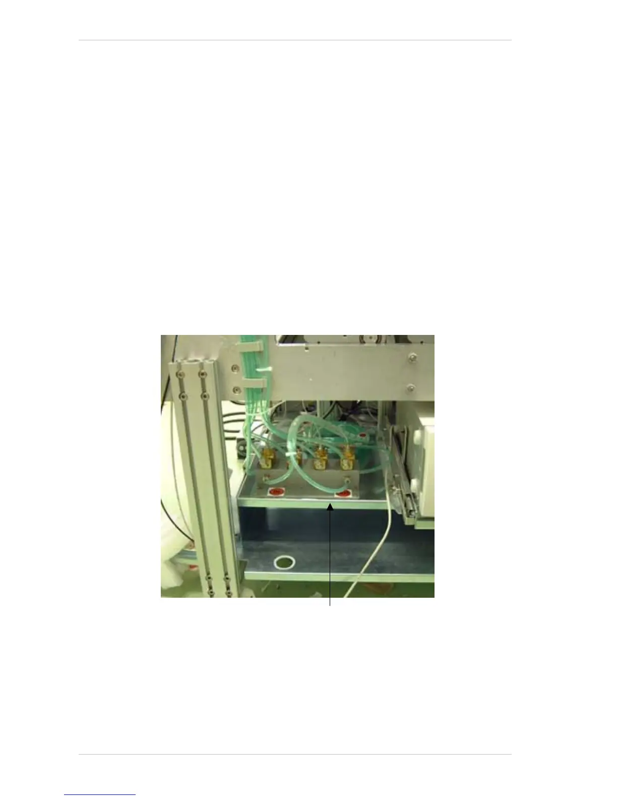
The liquid is cooled by the cooler and is pumped via the L
IQUID COOLING
CONTROL BOX (Figure 3-5) to each of the four aluminum profiles that
support the T
HERMAL PRINT HEADS (Figure 3-6, page 3-5). The LIQUID
COOLING CONTROL BOX is located on the left side of the printer, behind the
PC Door (Figure 3-1, page 3-2), as illustrated below
Figure 3-5: The Liquid Cooling Control Box
Liquid Cooling Control Box