20 TM1700-SERIES ZP-BL16E BL1448GE
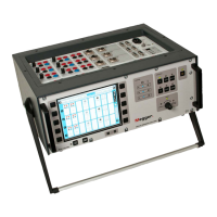
3 SYSTEM OVERVIEW
Terminal configuration
The terminals are grouped in three similar parts A,B
and C suited for 3-phase operation (L1 L2 L3, RST).
Red recommended for plus voltage
Black recommended for minus voltage
❹ Timing M/R
The Timing M/R section measures timing on Main and
Resistive (parallel) contacts. The section measures up
to six breaks with both main and resistive contact, giv-
ing in total 12 measuring channels. All three connec-
tors (phases) are galvanically isolated and have built-in
voltage source.
Terminal configuration
The section is equipped with three XLR female con-
nectors named A, B and C. Each connector has three
poles for connection to two breaks.
1 First break point
2 Second break point
0 Common point for both breaks
❺ Analog
The Analog section is for measurement of motion,
voltage, current, vibration, density, pressure etc.
The channels are for motion measurements with
standard linear or rotary transducers (resistive analog
type), shunts and 4-20 mA transducers.
The connectors are XLR male. Transducer cable with
female XLR contact.
Terminal configuration
The terminals are grouped in three similar parts A,B
and C suited for 3-phase operation (L1 L2 L3, RST).
As an option this section can be configured with three
extra analog channels.
Cable with female XLR contact needed, included in
the delivery of the instrument.
0 earth
IN input value from transducer
OUT output from unit to transducer
❻ Digital
Digital channels are for measurement of motion, both
linear and rotary with incremental/digital transducer.
▪
Number of channels 6
▪ Measurement ranges transducer resolution up to +/-
32000 pulses.
Terminal configuration
The terminals are grouped in three similar sections A,B
and C suited for 3-phase operation (L1 L2 L3, RST).
IMPORTANT
Make sure that the transducer you con-
nect has the correct pin configuration.
Wrong configuration can damage the
instrument.
❼ DC OUT
12 V, 0.5 A DC
❽ DRM
Contact or voltage output to DRM injection control
unit. Settings are made from CABA Local or CABA
Win if installed. The contact or voltage mode is indi-
cated on the output terminals.
❾ DCM1700 (optional accessory)
Connector for the external optional DCM MODULE
that uses a measuring technology called Dynamic
Capacitive Measurement. The DCM module together
with the Timing M/R section measures timing on up to
six breaks (e.g. three phase circuit breakers with two
breaks per phase) with both sides grounded, Dual-
Ground™ technology.
Using the DCM1700 MODULE and the DualGround technol-
ogy makes testing a lot safer.
 Loading...