72 TM1700-SERIES ZP-BL16E BL1448GE
6 APPLICATION EXAMPLES
6
Application examples
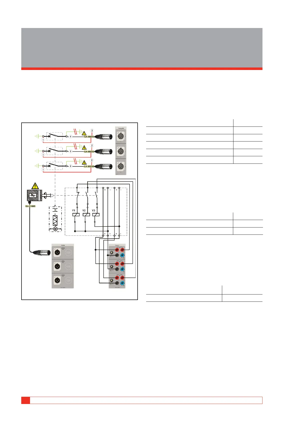
6.1 Example 1
3-phase circuit breaker with single
interrupter per phase and common
operating mechanism
How to connect
Test quantities
▪ Main contact timing measured by the Timing M/R section
▪ Auxiliary contact timing (one a & one b contact) measured
by the Control section
▪ Coil current & voltage measured by the Control section
▪ Main contact motion & velocity
Transducer in use
▪ Linear, resistive, 150 mm
Others
▪ No resistor contacts, no grading capacitors
Necessary settings in Breaker View
Breaker View
Number of phases 3
Operating mechanism Common
Number of interrupters per phase 1
Resistor contacts None
Number of a-contacts 1
Number of b-contacts 1
Breaker View \ Pulse & Delay Times
These settings are depending on the circuit breaker
type. If you are uncertain please refer to the breaker
manufacturers data.
Breaker View \ Measurement Preferences
Coil current On
Control voltage On
Static voltage On
Breaker View \ Measurement Preferences \
Measurement Time & Sample Interval
The default settings should be sufficient in most of
the cases.
Breaker View \ Measurement Preferences \
Motion Measurement Preferences
Transducer type Linear, Resistive
Absolute (calibrated transducer) On
Breaker View \ Measurement Preferences \
Motion Measurement Preferences \ Speed
Calculation points
Whenever possible do settings according to manufac-
turers definition. However if that is not available you
can make your own choice and use it as your own
reference.
 Loading...