BL1448GE ZP-BL16E TM1700-SERIES
19
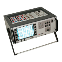
3 SYSTEM OVERVIEW
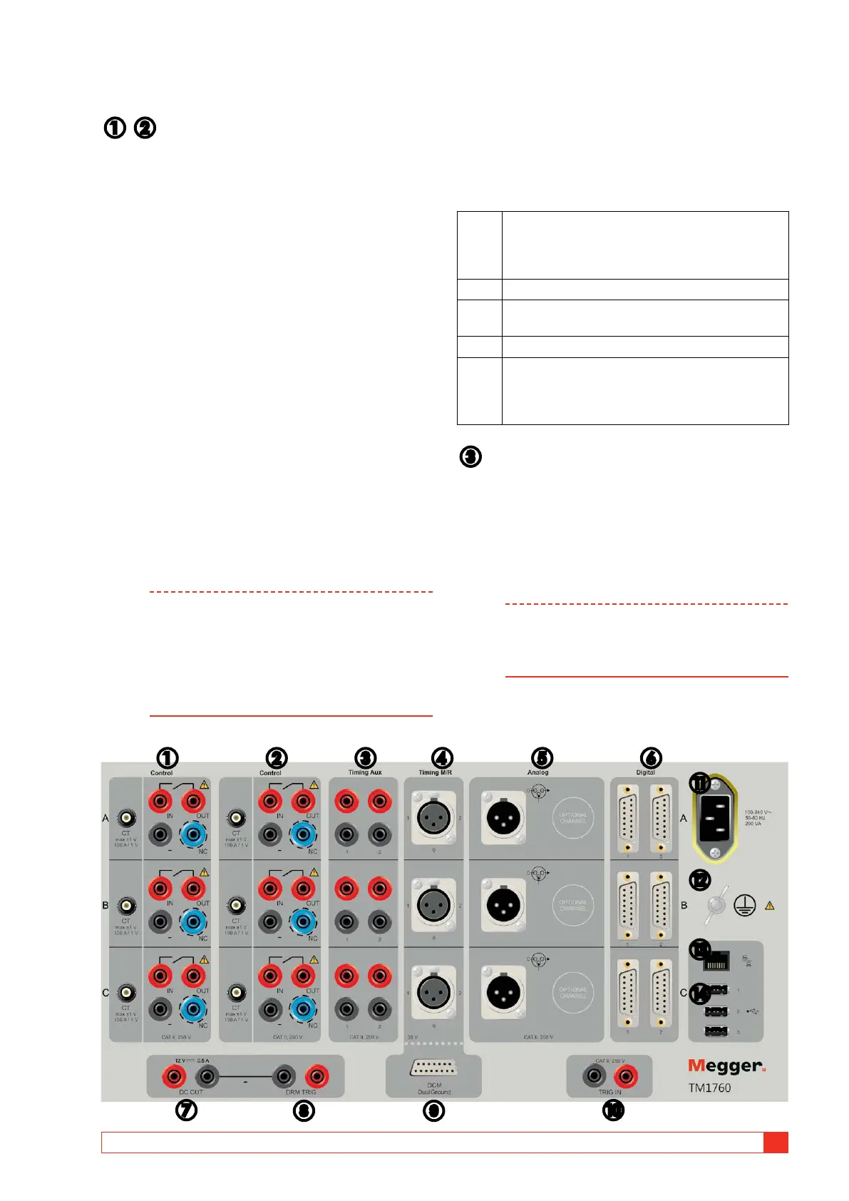
3.3 Top panel
❶ ❷ Control
The Control sections controls the operation of the cir-
cuit breaker. It gives a pulse to the coil for close, open
and for the motor operation. The sections has three
contact closures, one for each phase. For 1-phase
operation use phase A for close and phase B for open.
If two sections are used you can have 3-phase opera-
tion with separate voltage for all phases and close and
open operation. You can use the same voltage for all
operations, just connect inputs in parallel.
The start and stop of the pulse is set in CABA Local or
in CABA win.
During use control sections measure coil current and
battery voltage (supply voltage to coils) and timing of
auxiliary contacts in control circuit of circuit breaker.
The coil resistance can also be measured.
▪
Three independent contact functions per section.
▪ Sequences C, O, C-O, O-C, O-C-O.
▪ The function of the sequence is set in CABA Local or
CABA Win.
▪ Station auxiliary voltage measurement (when station
battery voltage is used for operation)
Note Auxiliary contact timing is measured for single
operation. Depending on time lapse between
O and C pulse timing may work for combined
operations. When there are auxiliary contacts
in series the result is dependent on both con-
tacts and it is not possible to distinguish each
contact separately.
Terminal configuration
The section has safety connectors. Use cables with
touch-proof plug contacts. The terminals are grouped
in three similar parts A,B and C suited for 3-phase
operation or for close, open and motor operations in
1-phase system.
CT Input for external clamp-on CT with an output of
max ±1 V and a scaling of 100 A / 1 V. The inter-
nal current measurement is disconnected when a
BNC test lead is connected.
IN Connect to the supply (+)
OUT Connect to close/open circuit of the circuit
breaker
– Connect (-) if needed
NC (No Connection) This is a blind terminal that can
be used for temporary placement, for safety, of
cable plugs when you want to disconnect coil
circuits.
❸ Timing aux
Measures timing of up to six (6) auxiliary contacts in
voltage or contact mode. For example:
▪
a and b contacts timing
▪ Spring charging motor timing
▪ Anti-pump contact timing
Note When at least one a and one b contact is
selected in Breaker View the a and b contacts
in the coil circuit are measured automatically
by the Control section.
When more than one a or b contact is selected the
Timing Aux section will be used to measure the re-
maining contacts.
❶ ❷ ❸ ❹ ❺ ❻
⓫
⓬
⓭
⓮
❼ 8 9 ❿
 Loading...