SECTION - 6 DRIVE SYSTEM AND ENGINE INSTALLATION
90-899883183 DECEMBER 2007 Page 43 / 54
3. Push the dribble valve stem in until gear lube appears, then release.
a
7851
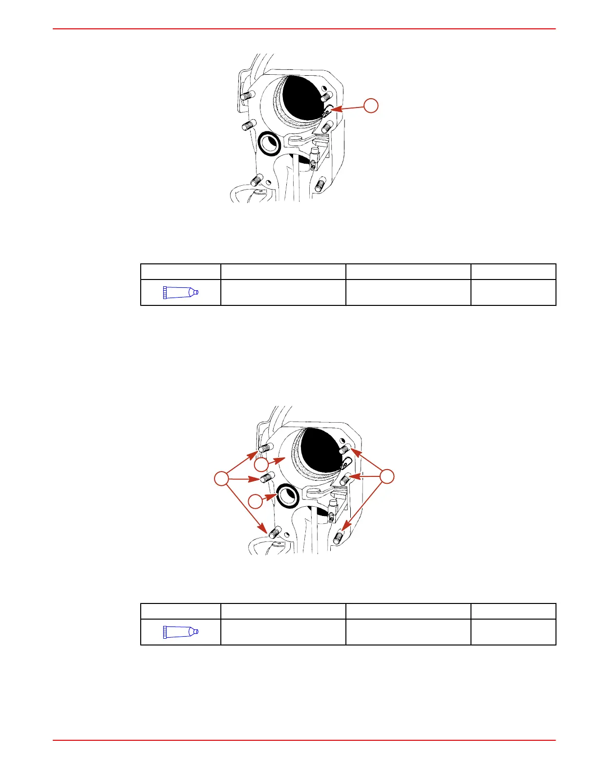
a - Dribble valve stem
4. If the gear lube monitor is below the "OPERATING RANGE" line, fill the gear lube monitor with
specified fluid. Do not overfill.
Tube Ref No. Description Where Used Part No.
87
High Performance Gear
Lubricant
Gear lube monitor 92-858064K01
5. Install the gear lube monitor cap. Ensure that the rubber gasket is inside the monitor cap. Do
not overtighten the cap.
IMPORTANT: Position the rubber gasket properly in the bell housing bore before installing the
drive unit to prevent water leaking into the boat.
6. Ensure that the rubber gasket and water passage O‑ring are properly positioned in bell
housing.
7. Coat the bell housing studs with lubricant.
a
7852
c
c
b
a - Rubber gasket
b - Water passage O‑ring
c - Studs (6)
Tube Ref No. Description Where Used Part No.
95
2-4-C Marine Lubricant with
Teflon
Bell housing studs 92-802859A 1

 Loading...
