CHARGING & STARTING SYSTEM
90-855347R1 JANUARY 1999 Page 2B-29
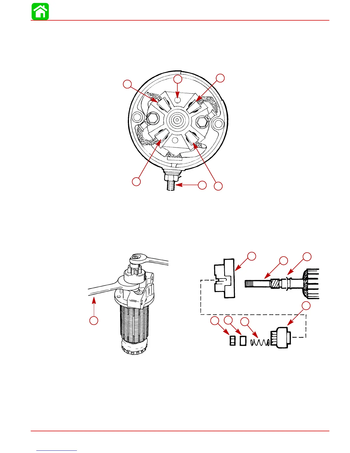
4. Brush replacement is recommended if brushes are pitted, chipped or worn to less than
0.25 in. (6.4 mm). If necessary, remove brushes as follows:
a. Remove hex nut and washers from POSITIVE (+) terminal and remove POSITIVE
brushes and terminal as an assembly.
b. Remove 2 bolts securing NEGATIVE (–) brushes and brush holder to end cap.
11656
b
c
b
d
c
a
a
b
c
c
b
d
a-Brush Holder
b-Positive Brushes
c-Negative Brushes
d-Positive Terminal
5. Remove armature (with drive end cap) from starter frame.
6. Remove locknut and remove drive assembly from armature shaft.
11658
e
f
g
d
c
b
a
a
51711
b
c
d
e
f
g
h
a
a-Hold Armature Shaft with Wrench on Hex Portion of Drive Assembly
b-Locknut
c-Spacer
d-Spring
e-Drive Assembly
f-Drive End Cap
g-Armature Shaft
h-Washer

 Loading...


