POWERHEAD
Page 4A-30 90-855347R1 JANUARY 1999
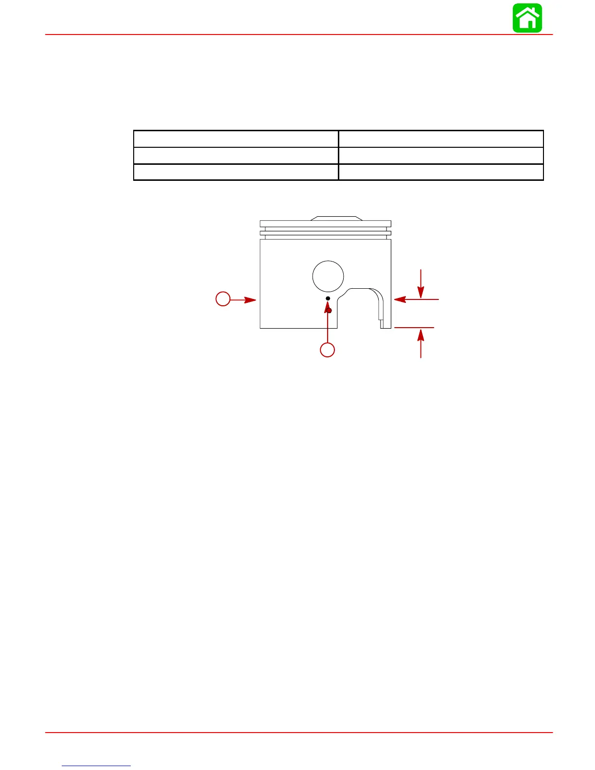
MEASURING PISTON ROUNDNESS
Piston has a barrel profile shape and is not a true diameter.
Standard 135/150 Models - 153 cu. in. (2508 cc)
1. Using a micrometer, measure dimension “A” at location shown. Dimension “A” should
be as indicated in chart following.
Piston Dimension “A”
Standard Piston 3.4925 in. ± 0.0005 in.
0.015 in. Oversize Piston 3.5075 in. ± 0.0005 in.
2. Using a micrometer, measure dimension “B” at location shown. Dimension “B” should
be within 0.008 in. of dimension “A.”
0.700 in.
(17.78mm)
a
b
a-Dimension “A” at RIGHT Angle (90°) to Piston Pin
b-Dimension “B” (in line with Piston Pin)
Cylinder Heads and Exhaust Divider Plate
1. Inspect internal surface of cylinder heads for possible damage (as a result of piston
or foreign material striking cylinder heads).
IMPORTANT: Cylinder head warpage should not exceed 0.004 in. (0.1 mm) over the
ENTIRE length of the cylinder head. If measured warpage, as determined on a sur-
face block, exceeds 0.004 in. (0.1 mm) or a discontinuity of up to 0.004 in. (0.1 mm)
exists in a narrow portion of the cylinder head’s surface length, then the cylinder
head may be re-surfaced up to 0.010 in. (0.25 mm).
2. Replace cylinder head(s) as necessary.
3. Thoroughly clean gasket surfaces of exhaust divider plate.
4. Inspect exhaust divider plate for deep grooves, cracks or distortion that could cause
leakage. Replace parts as necessary.
Crankshaft
1. Inspect crankshaft to drive shaft splines for wear. (Replace crankshaft, if necessary.)
2. Check crankshaft for straightness. Maximum runout is 0.006 in. (0.152 mm). (Replace
as necessary.)
3. Inspect crankshaft oil seal surfaces. Sealing surfaces must not be grooved, pitted or
scratched. (Replace as necessary.)
4. Check all crankshaft bearing surfaces for rust, water marks, chatter marks, uneven
wear and/or overheating. (Refer to “Connecting Rods”.)
 Loading...


