POWERHEAD
90-855347R1 JANUARY 1999 Page 4A-45
8. Remove screws and connecting rod cap from piston rod assembly being installed.
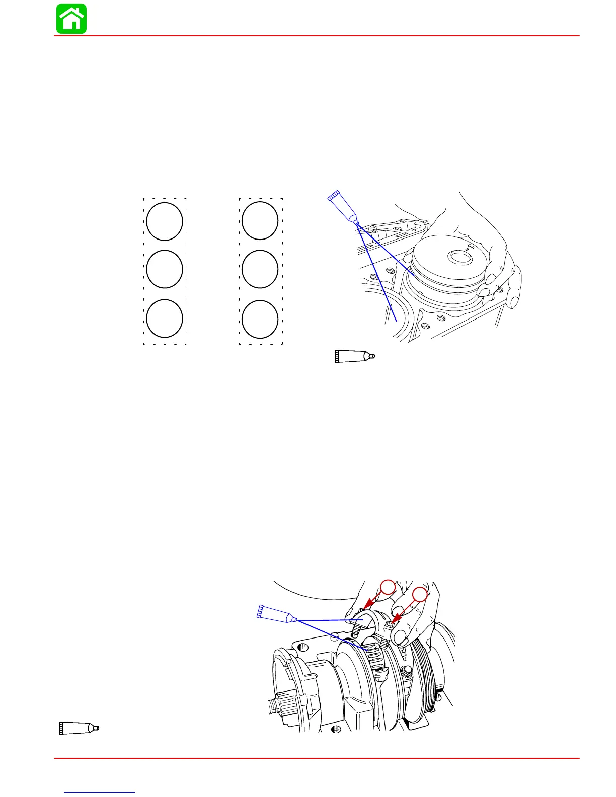
IMPORTANT: Piston must be correctly installed and positioned as shown.
Pistons marked with the word “UP” and with the letter “P” or “S” on top of piston.
Pistons with the letter “P” must be installed in the port side of engine and the word “UP”
facing toward top of engine.
Pistons with the letter “S” must be installed in the star- board side of engine and the word
“UP” toward top of engine.
9. Coat cylinder bore with 2-cycle oil. Match piston assembly with cylinder it was re-
moved from, and position piston as described below. Push piston into cylinder.
56156
CYL 2
CYL 4
CYL 6
CYL 1
CYL 3
CYL 5
UP
P
UP
P
UP
P
UP
S
UP
S
UP
S
14
14
2 Cycle Outboard Oil (92-826666A24)
10. Apply Quicksilver 2-4-C w/Teflon to bearing surface of connecting rod and install bear-
ing assembly, as shown.
11. Place connecting rod cap on connecting rod. Apply light oil to threads and face of con-
necting rod bolts. Thread connecting rod bolts finger-tight while checking for correct
alignment of the rod cap as shown.
IMPORTANT: Connecting rod and connecting rod caps are matched halves. Do not
torque screws before completing the following procedure.
• Run a pencil lightly over ground area.
• If pencil stops at fracture point, loosen bolts, retighten, and check again.
NOTE: If you still feel the fracture point, discard the rod.
12. Tighten connecting rod bolts (using a 5/16 in. - 12 point socket). First torque to 15 lb.
in. (1.7 N·m) then 30 lb. ft. (41 N·m). Turn each bolt an additional 90° after 2nd torque
is attained. Recheck alignment between rod cap and rod as shown.
a
a
51850
a
a
95
2-4-C With Teflon (92-825407A12)
95
a-Connecting Rod Screws
 Loading...


