MI 3152(H) EurotestXC (2,5 kV) Tests and measurements
120
Measurement procedure
Enter the Z line function.
Set test parameters / limits.
Connect test cable to the instrument.
Connect test leads or Plug commander to the object under
test, see Figure 7.43.
Save results (optional).
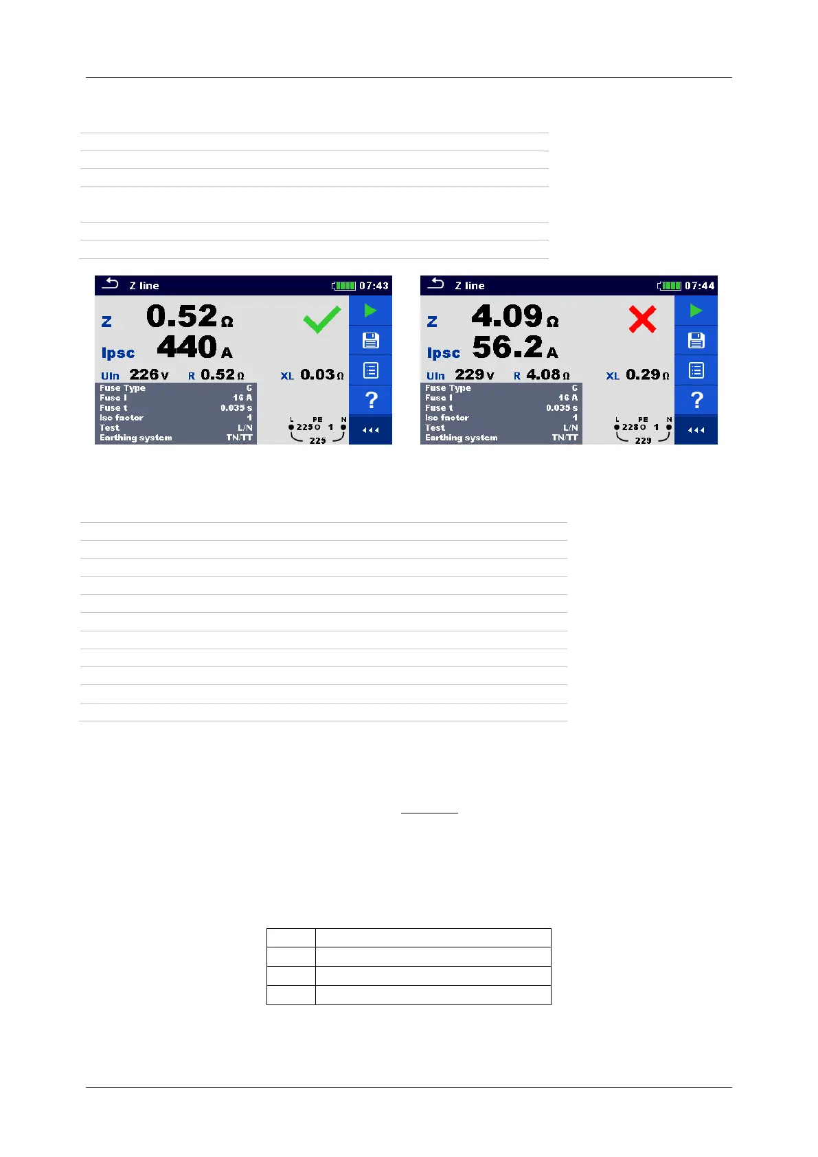
Figure 7.44: Examples of Line impedance measurement result
Measurement results / sub-results
Prospective short-circuit current
Voltage measured between L/L1 – N/L2 test terminals
Resistance of line impedance
Reactance of line impedance
Maximal three-phases prospective short-circuit current
Minimal three-phases prospective short-circuit current
Maximal two-phases prospective short-circuit current
Minimal two-phases prospective short-circuit current
Maximal single-phase prospective short-circuit current
Minimal single-phase prospective short-circuit current
Prospective short circuit current I
PSC
is calculated as follows:
where:
U
n
......... Nominal U
L-N
or U
L-L
voltage (see table below),
k
sc
........ Correction factor (Isc factor) for I
PSC
. Refer to chapter 4.6.5 Settings for more
information.
Input voltage range (L-N or L-L)
Table 7.5: Relationship between Input voltage – U
L-N(L)
and nominal voltage – U
n
used for
calculation

 Loading...