13
Please read the following information about magnet spacing and
polarity.
The number of magnets that must be used depends on the size
of your tire and where you mount the sensor. On tractor or
implement wheels the general rule of thumb is one magnet for
each wheel bolt (minimum of two, and
always an even
number).
For drive shafts or small wheels (ATV’s), two magnets
are usually adequate.
Some installations may require that more than two magnets be
installed. To determine the number of magnets required,
measure the distance traveled of one revolution of the sensor
equipped wheel in inches (centimeters).
See the following tables to find the minimum number of
magnets r
equir
ed (alw
a
ys an even number) -
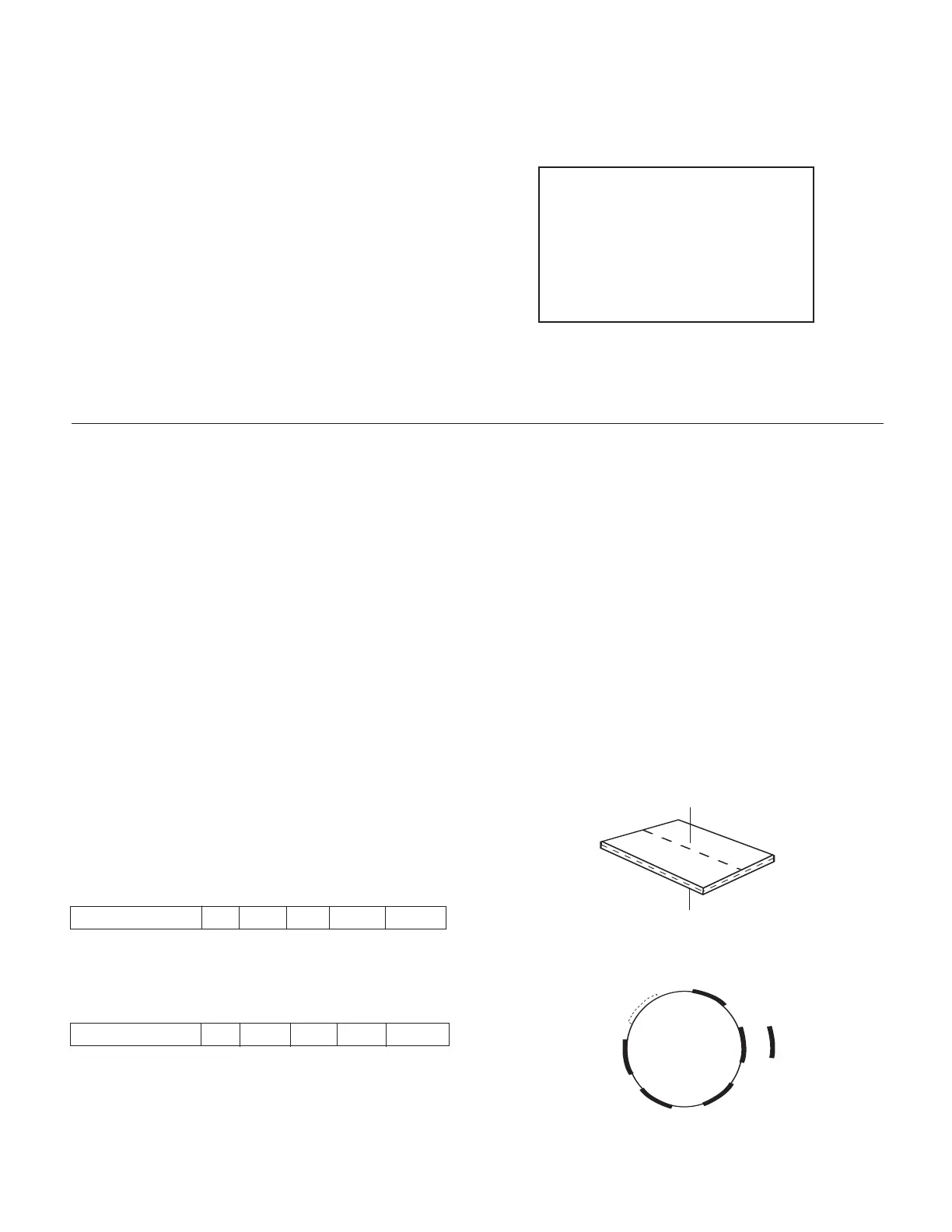
The magnets provided by Micro-Trak are marked with a
punched dashed line on the SOUTH pole side of the magnet.
See Illustration 5A.
Always use an even number of magnets, and always
alternate the polarities of the magnets as you go around
the wheel hub or drive shaft.
To install, mount the first magnet with the SOUTH pole side
(dashed line) facing toward the hub or shaft.Mount the second
magnet with the NORTH pole side facing toward the hub or
shaft. See Illustration 5B.
For proper operation, the magnets must be evenly spaced
around the wheel or drive shaft. The magnets must be at least
1" apart.
See Illustration 5C.
Magnets
Illustration 5A
P
lease Note: If you have purchased an Astro GPS Speed
Sensor or a Vansco radar speed sensor, disregard the
following section on magnetic speed sensors and install
the speed sensor as described in the instructions
included with the unit. You may need an adapter cable
to connect to some radars, see Appendix E.
Speed Sensor Installation
Locations where the sensor may be installed:
1. Non-driven wheel on tractor, vehicle or implement. This is
less susceptible to errors resulting from wheel slip.
2. Tractor, vehicle or planter drive shaft.This type of mounting
is recommended for trucks, four-wheel drive tractors or
other equipment that has poor or no access to a non-driven
wheel.
Locate the following parts:
Speed sensor cable (Green body)
Mounting “L” bracket
Magnets
Cable ties
North
S
outh
N
or
th
North
S
outh
South
1
2
3
4
5
6
Illustration 5B
Test magnet
should alt
ernately
a
ttract and repel.
S
N
E
nglish or
T
ur
f (inches)
W
heel C
ircumference: 40 80 120 160 200
Number of Magnets: 2 4 6 8 10
Metric (cm)
W
heel Circumference: 100 200 300 400 500
Number of Magnets: 2 4 6 8 10
 Loading...

