25
Drive Shaft Speed Sensor Calibration
Any number between 10 and 15 (255 mm to 380 mm) is a good
starting value.
NOTE: For fine-tuning the SPEED CAL value, see Appendix B on
pages 45-46.
NO
TE: If you have mounted the magnetic speed sensor on a
wheel, skip this step and go on to Fine Tuning
Speed/Distance Calibration Values.
Because of the difference in wheel-to-drive shaft ratios, it is
difficult to determine a calibration value for installation on a
drive shaft by measuring a wheel. You must start with an
estima
ted calibration value and then fine-tune the calibration.
Illustration 16
Determining the SPEED CAL (Skip this section if using radar or GPS speed sensor)
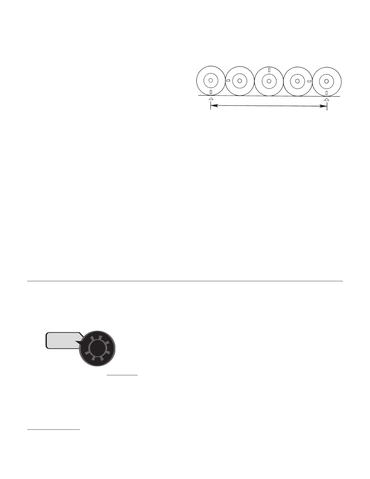
To determine SPEED CAL, measure the distance of
one complete wheel revolution and divide by the
number of magnets installed.
For the console to calculate the correct speed and measure
distance accurately, the circumference of the sensor-equipped
wheel must be entered. Determine the circumference of the
sensor-mounted wheel to the nearest tenth of an inch (tenth of a
centimeter) with the following method:
METHOD: M
ark the tire with a piece of chalk and measure the
distance traveled on the ground for one complete revolution.
See
Illustration. For improved accuracy, it is recommended that you
perform this function in field conditions, measure several
revolutions, and take the average.
Divide the measured revolution by the number of magnets
installed to get your starting SPEED CAL calibration value. Once
calibration of the system is complete, this number should be fine-
tuned for optimum accuracy.
For fine-tuning the SPEED CAL value, see Appendix B on pages 45-46.
MIN FLOW: The purpose of this calibration value is to
prevent the system from applying below the recommended
minimum rate for the nozzles. The minimum flow rate in
gallons per minute (liters per
minut
e) based on the
nozzles being used, for
the en
tir
e b
o
om on the
sprayer.
DO NOT enter
the actual flow of
your spray application.
For example: If the minimum
flow rate for the nozzle you are using is .22 GPM at their
minimum recommended pressure and your boom has 20
nozzles, enter 4.4 as the MIN FLOW value (.22 x 20 = 4.4). The
sy
stem
WILL NO
T
apply a
t a rate lower than this value when
spr
a
ying in A
UT
O
.
T
his v
alue should be checked/ changed for
each diff
er
en
t nozzle that you use.
APPLICATION NOTE: Over-application may occur with MIN
FLOW set if ground speed is too slow.