38
CONSOLE INPUTS:
If there is no response from any of the following tests, refer to the
main wiring diagram to locate the next connector in line toward the
console and repeat the test at that connector. If there is a response
at that connector,the problem may be in the cable between the two
connectors (or the connectors themselves).
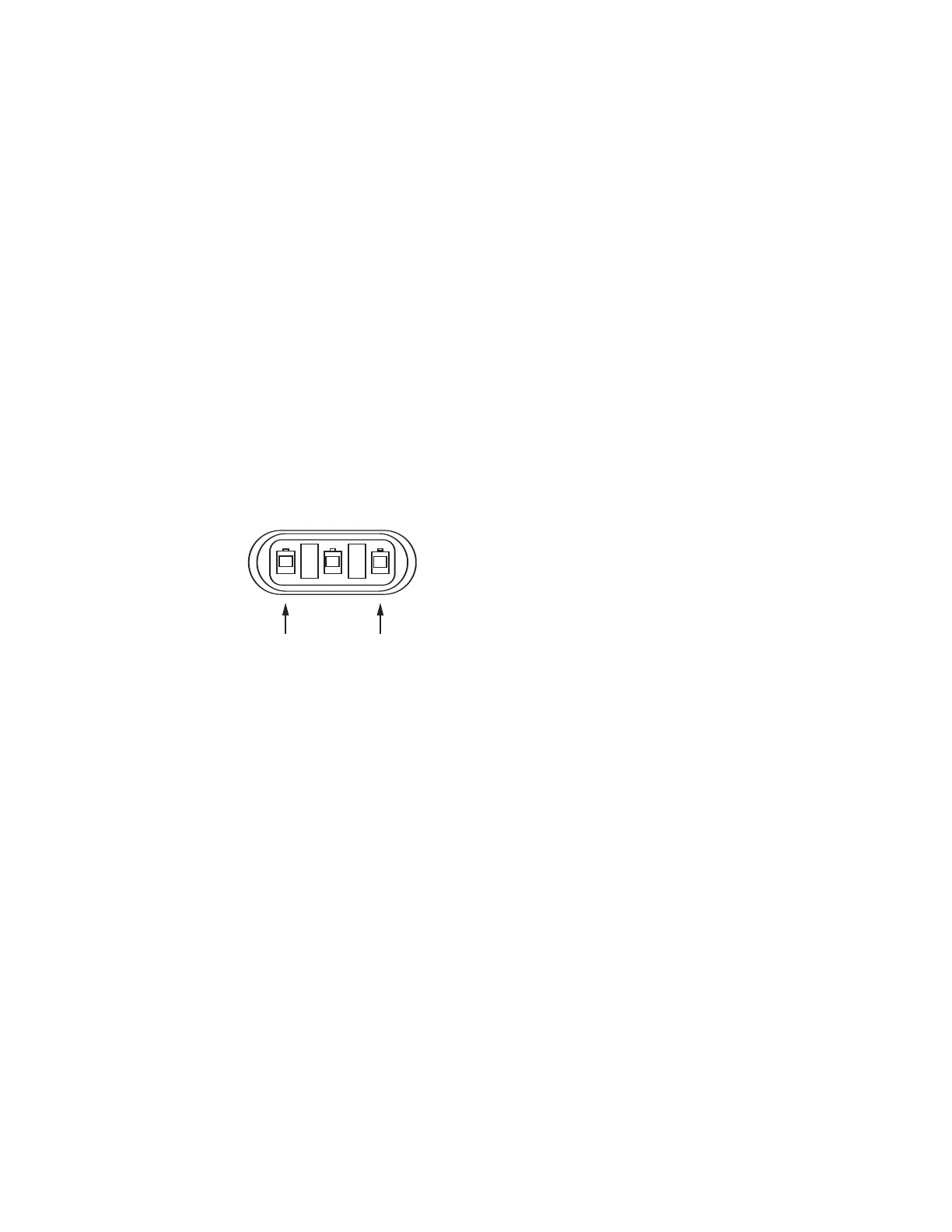
SPEED INPUT: Turn rotary switch to speed position and dis-
connect the speed sensor (yellow tie) from the main harness.
Check for 12 volts between pins B (white) and C (black) of the
main harness speed cable (yellow tie). Using a clip lead or
other jumper wire (such as a paper clip bent in a “U”), several
times rapidly short together pins A (red) and C (black) of the 3-
pin connector
(See Illustration 18). The console should respond
with some speed reading.
FLOW INPUT: Turn rotary switch to VOLUME/MINUTE and
disconnect the flow sensor (green tie) from the main harness.
Check for 12 volts between pins B (white) and C (black) of the
main harness flow cable (green tie). Using a clip lead or other
jumper wire (paper clip bent in a “U”),several times rapidly short
together pins A (red) and C (black) of the 3-pin connector. The
console should respond with some flow rate reading.
REMOTE RUN/HOLD INPUT: Disconnect the remote
run/hold sensor (or jumper cover) from the main harness.
Check for 12 volts between pins B (green) and C (violet) of the
main har
ness remote run/hold cable (grey tie). Placing a clip
lead or other jumper wire (such as a paper clip bent in a “U”)
between pins A (blue) and C (violet) of the main harness
run/hold connector (grey tie) should turn off the “HOLD” icon
on the console display. Removing the jumper should turn on
the “HOLD” icon on the console display.
FLOWMETER:
Shaking the Flowmeter end to end should produce a “rattling”
sound (shaf
t end pla
y).Blowing in the meter from either end should
spin the turbine fr
eely
.
I
f the turbine spins fr
eely but the met
er will
not register flow with a known working sensor, the turbine may be
defective. See Flowmeter Assembly and cleaning on page 49 for
details
.
SER
V
O
V
ALVE CONTROL SIGNAL:
With the console turned ON, put the console in MANUAL mode,
place the remote Run/Hold switch in the RUN position and turn at
least one boom switch to ON.Using a voltmeter or simple test light,
check from a good frame ground to each of the servo wires on the
main har
ness connector. You should get 0 volts on each wire.
H
olding the
“+”
butt
on should c
ause the RED wir
e t
o pulse t
oward
12 volts (light will pulse). Holding the “-” button should cause the
BLACK wire to pulse toward 12 volts (light will pulse).
Troubleshooting (Continued)
Three-Pin Connector
Illustration 18
SERVO VALVE:
The best way to test the servo valve is with a known working
console. Turn console ON, put the console in MANUAL mode,
place the remote Run/Hold in the RUN position, turn the rotary
switch to RATE and turn at least one boom switch to ON. With
the servo valve connected to the servo valve lead on the main
harness, holding the “+” button should close the servo valve
and holding the “-” button should open the servo valve NOTE:
assuming you are in bypass configuration (provided the
console has passed the Servo Valve Control Signal test). The
servo valve should operate smoothly in both directions, from
fully open to fully closed.
You may also use a 9-volt transistor battery. Connecting the
battery to each terminal on the servo valve should cause the
servo valve to run in one direction. Reversing the battery
connections should cause the servo valve to run the other
direction. The servo valve should operate smoothly in both
directions, from fully open to fully closed.
PLUMBING:
Proper plumbing is a very important factor in obtaining
optimal performance from your SprayMate II system.The chart
on the next page will help you determine what area of the
plumbing may be causing your problem. At this point, it is
assumed that your plumbing basically matches that of the
system diagram and that the servo valve and flowmeter are
known to be installed correctly and functioning properly. In
addition, make certain that you have selected and installed the
correct spray tips for the application,speed and spray rate that
you intend to maintain. Don’t forget the obvious such as leaky
fittings and hoses, pinched hoses and plugged or worn
nozzles.If you need more detail than the chart provides,please
refer to Plumbing Guidelines on pages 39 - 41.