45
NOTE: This is an optional method generally used on
p
ickups or custom vehicles. It may also be necessary on
any other vehicles where access to the wheels is
limited. This installation requires a fine tuning
procedure, see pages 46-47.
Determine the best location for the magnets on drive shaft
according to which is the most practical spot to attach sensor
mounting bracket.This position should be no more than 12" (.30
meters) behind the front U-joint. For best results, mount “L”
bracket to transmission and mount magnets on drive shaft as
close to transmission as possible. This will ensure proper
alignmen
t if drive train shifts under heavy loading.
T
wo magnets are required for proper Hall-effect speed
sensor operation. Position them exactly opposite each other
(180 degrees apart).The polarity (north and south poles) detect-
ed by the Hall-effect speed sensor must alternate as the shaft is
turned. The magnets provided by Micro-Trak are marked with a
punched dashed line on the SOUTH pole side of the magnet.
• Attach magnets onto drive shaft, one NORTH pole side out
and the other SOUTH (dashed) pole side out,by wrapping ca-
ble tie around shaft and magnets. Position each magnet so
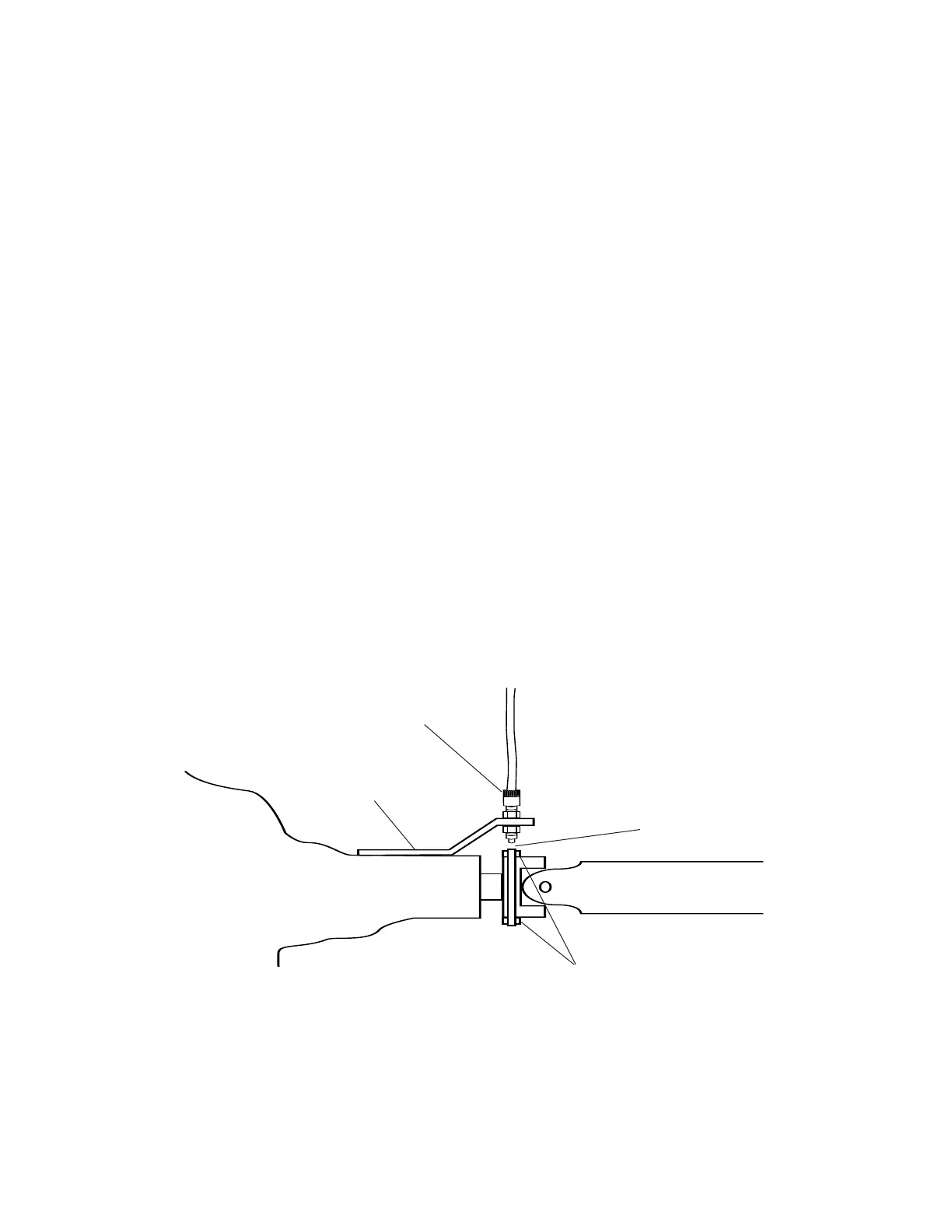
Transmission/ Transfer Case Drive Shaft
Fasten sensor bracket with
existing transmission bolts,
or rigidly attach with clamps.
1/4" to 1/2"
(6mm to 3mm)
spacing
Magnets positioned
180º apart
Sensor body
(GREEN)
that its longest dimension moves in the direction of
rotation. Pull cable tie tight and trim off excess. An adjust-
able, non-magnetic (stainless steel) band clamp may also be
substituted.
• Attach sensor bracket to vehicle transmission.
See
Illustration below. Use either the short or long end of the
bracket as a base.
• Turn one locking nut onto threaded sensor and insert sensor
into large hole selected on mounting bracket. Turn on
remaining locking nut. Set sensor to proper distance from
magnets (1/4" to 1/2", or 6mm to 13mm). When distance is
set
, tighten nuts to lock sensor in place.
• Secure sensor cable to frame with cable ties. Place first tie as
close to sensor assembly as possible.
See SPEED CAL on page 25.
Optional Speed Sensor Mounting on Drive Shaft
Appendix A: cont.