49
IMPORTANT: Opening the flowmeter will void the Flowmeter
Calibration value assigned to your unit. However, you may need to
take the flowmeter apart for periodic cleaning or to remove an
obstruction.
If you can shake the flowmeter from end-to-end to produce a
“rattling” sound (shaft-end play), or if you can blow into the meter
from either end and cause the turbine to spin freely,your flowmeter
does not need cleaning.If you cannot hear the “rattling”sound or get
the turbine to spin freely, your flowmeter
needs to be cleaned. See
Illustrations below for reassembly instructions.
OPENING THE FLOWMETER:
Cut the calibration tag retaining wire. Remove the screws and
disassemble the flowmeter. Do not attempt to remove the sleeve
bearings from the flowmeter housing.
U
se warm water and if necessary, a mild detergent and a soft bristle
brush to clean all parts.
Do not use solvents or diesel fuel to clean
the flowmeter. A magnet works well for removing fine metallic
particles from the turbine.
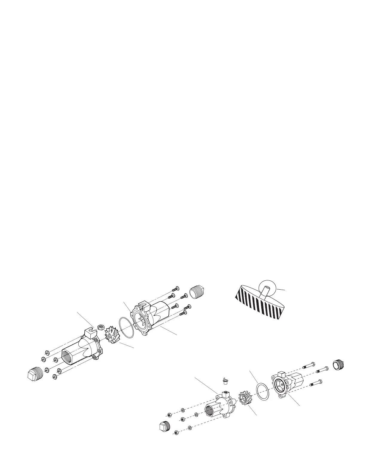
Inspect all parts.Check for excessive bearing or shaft wear.The shaft
will wear shorter until the turbine drags on the housing. Illustration
19 shows you what a new shaft looks like.When the shaft is worn
to the point of drag,the turbine must be replaced.
On a flat surface, place each housing half on end. Set and spin
the turbine in each half. It should spin freely. If it does not spin
Quad-Ring
P/N 13783
Housing FM750 GFN
Housing FM750 GFN
(N
on sensor)
Turbine
P/N 14836
freely, remove the turbine,wipe the shaft and try again. If is still
does not spin freely, the shaft or bearings may have excessive
wear. (Service may be necessary.)
ASSEMBLING THE FLOWMETER:
Stainless steel meters use a Teflon gasket. Sealants are normally
not required. Plastic meters use an o-ring (Quad-ring). Apply a
small amount of silicon grease for lubrication. Gaskets and o-rings
may be reused several times but eventually may need
replacement.
Place the turbine in the non-sensor housing. Position
gasket / o-ring; carefully place sensor housing over
turbine. Drop all screws into holes. Hold nuts (and lock washers
on stainless meters) in place and finger-tighten screws. Ensure
proper placement of gasket / o-ring and evenly tighten all screws.
Attach tag.
After assembly, shaking flowmeter end-to-end should produce a
“rattling” sound (shaft end play). Blowing into the meter from
either end should cause the turbine to spin freely. If the turbine
only spins from one direction, install the flowmeter so that the
liquid flows in that direction (service may be required).
For maximum accuracy the flowmeter should be mounted in a
vertical position. Recalibration is required before field operation.
Complete assembly
FM750 GFN Flowmeter
G
asket
P/N 10137
H
ousing FM750 SS
Housing FM750 SS
(Non sensor)
T
urbine
P/N 14836
New Shaft
Complete assembly
FM750 SS Flowmeter
Flowmeter Assembly
Appendix D: