46
Appendix B:
This procedure is used to verify the calibration of systems WITH the
Run/Hold Switch Kit or an optional remote run/hold kit installed.In
order to achieve accurate measurements, each step in this fine
tuning procedure should be performed as precisely as possible.
Note: If your system does not have a run/hold switch kit or remote
Run/Hold sensor installed,refer to next page for instructions.
Preparation:
• Once the system is fully installed and calibrated, select a
straight tract of ground that is similar to your actual field
c
onditions and as level as possible.
NOTE: Using a course with a different ground surface,
such as a hard-surface road, will result in different read-
ings than exact field conditions.
• Measure a distance of 1000 feet (500 meters).Clearly mark the
beginning and end points with flags or something highly
visible to the operator.
Procedure:
1. With the console turned ON, place the Run/Hold switch in the
HOLD position. The HOLD icon will be displayed. Turn the
rotary dial to the “DISTANCE” position. Be sure the display
shows 0. If not, reset the distance counter by pressing and
holding “RESET” until the display returns to 0 (approximately
one second). The word CLEAr will be displayed when reset is
pressed.
2. You are now ready to drive the measured course. Pick a
location on the vehicle to use as a marker for starting and
stopping the distance counting function (door handle, mirror,
step, etc.). You should begin driving the course well ahead of
the starting flag and drive past the ending flag, using the
Run/Hold switch to start and stop the counting function. It is
not recommended to start from a dead stop at the starting
flag and stop at the ending flag.
3. Place the Run/Hold switch in RUN when the marker on the
v
ehicle passes the star
ting flag t
o activate the distance
counting function. The console display numbers will increase,
adding to the distance total as you drive. Drive the pre-
measur
ed c
ourse and plac
e the R
un/H
old switch in HOLD,
when the marker on the vehicle passes the ending flag,to stop
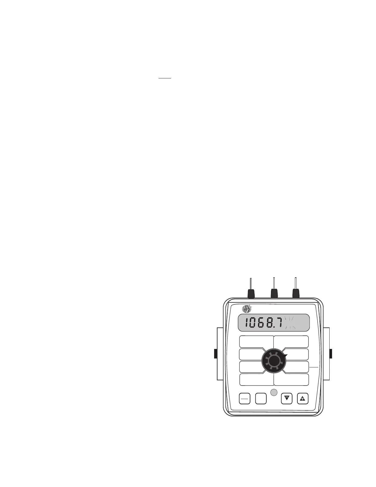
the distance counting function. The console display should
r
ead
“HOLD
”
.
S
ee Illustr
ation t
o the r
ight
.
S
t
op the v
ehicle in a
level and safe area and continue with this procedure.
4. With the rotary dial still at DISTANCE (SPEED CAL), press and
hold the “CAL”key for one second.Once the console is in “CAL,”
C
AL and the sp
eed c
alibr
a
tion v
alue will b
e displa
yed.
Momentarily press CAL and the word CAL will begin to flash
and the distance travelled will be displayed.
See illustration
below.
5. When the display shows distance (“CAL” is flashing), verify
whether the number displayed is the exact distance you
drove (within +/- 1 - 2 %). If not, press the “+”or “-” key to ad-
just the figure to match the distance you actually drove.If the
display reads too high, use the “-” key to lower the displayed
value. If the display reads too low, use the “+” key to raise the
displayed value.
6. When the number shown on the display matches (as closely
as possible) the actual distance driven,you have arrived at the
correct calibration value. If you cannot adjust the displayed
distance to exactly match the actual distance driven, adjust
the figure as close as possible to the actual distance.You may
check the calibration number by momentarily pressing CAL.
The word CAL and the SPEED CAL number will appear. Exit
“CAL” by pressing “CAL”for one second.
The speed sensor is now calibrated. To verify proper
calibration, repeat the procedure a second time. Write down the
new speed calibration number and keep it in a safe place. If the cal-
ibration values are ever accidentally changed, you can simply re-
enter this number.
Fine Tuning Speed/Distance Calibration Value (With Run/Hold Switch Kit
Installed)
WIDTH
CAL
FLOW
CAL
MIN
FLOW
ADJUST
RATE
TARGET
RATE
SPEED
CAL
INLINE
BYPASS
TEST
SPEED
VOLUME /
MINUTE
DISTANCE
AREA /
HOUR
VOLUME
(1) (2) (3)
RATE
SPEED
AREA
(1) (2) (3)
TANK
CAL
AUTO
MAN
RESET
CAL
1 2 3 4 5
S
pray
M
ate
II
™
HOLD