66
I
MPORTANT:
O
pening the flowmeter will void the Flow
Calibration value assigned to your unit. However, you may need
to take the flowmeter apart for periodic cleaning or to remove
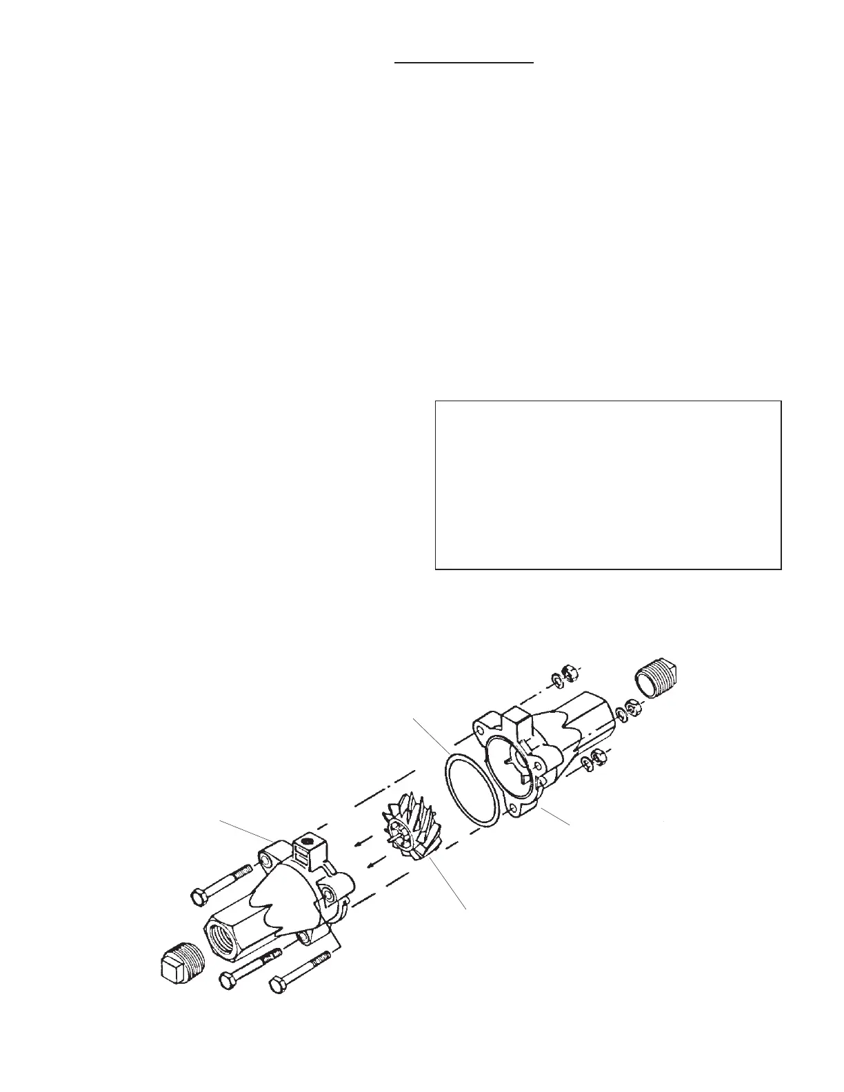
an obstruction. See illustration below for flowmeter reassembly
i
nstructions.
To open the flowmeter:
Disconnect the hose from servo valve to manifold. Loosen the
union hex closest to the heat exchanger. Remove the two “U”
bolts that hold the servo/flowmeter assembly to the brackets.
Unscrew the union from the heat exchanger and remove the
servo/flowmeter assembly.
Use running water to rinse the assembly of any accumulated
dirt. Remove the three flowmeter bolts, carefully open the
flowmeter and remove the turbine. Thoroughly clean turbine
and housings of any foreign material (dirt, pieces of teflon tape,
rust on magnets, etc.).
Set and spin the turbine in each flowmeter housing half. It
should spin freely. If not, remove the turbine, wipe the shaft and
try again.
To assemble the flowmeter:
Place the servo, flowmeter end up, in a vice or other suitable
fixture. Set turbine in non-sensor housing. Properly position
gasket on housing. (Gasket may be reused a few times but will
eventually need to be replaced.) Pipe thread compound is not
absolutely necessary but will insure a good seal. Be careful not to
get compound inside flowmeter or turbine will stall. Carefully
put other flowmeter housing (sensor half) in place. (Position the
G
asket pin
P/N 10137
Housing FM750 N with sensor
receptacle, includes bearing.
P/N 20294
H
ousing
,
includes b
ear
ing.
P/N 20294
Turbine
P/N 14836
Complete assembly
FM750 N Flowmeter
P/N 10899
housing so that the two square lugs are lined up with each
other.) Drop all three bolts into holes. Hold lock washers in place
and finger tighten all three nuts. Nuts should be torqued to 120
in./lb. (13.56 nw/m). Attach tag by running wire between a bolt
and the housings, and twisting.
After assembly, shaking flowmeter end-to-end should produce a
“rattling” sound (shaft end play). Blowing into the meter from
either end should cause the turbine to spin freely. If the turbine
only spins from one direction, install the flowmeter so that the
liquid flows in that direction.
Start with original calibration number and follow procedure in
manual for verifying flowmeter accuracy.
WARNING
TO PREVENT SERIOUS INJURY, DO THE FOLLOWING:
1. ALWAYS WEAR
gloves, goggles, and other necessary
equipment when handling NH3 apparatus.
2. DO NOT cross thread. Use anti-seize lead base thread
compound.
3. THOROUGHLY BLEED hoses before disconnecting NH3
apparatus.
4. COMPLETELY EVACUATE NH3 apparatus before servicing.
Appendix G: SprayMate II - NH3 Specific
Flowmeter Assembly (FM-750 N)