59
Appendix G: SprayMate II - NH3 Specific
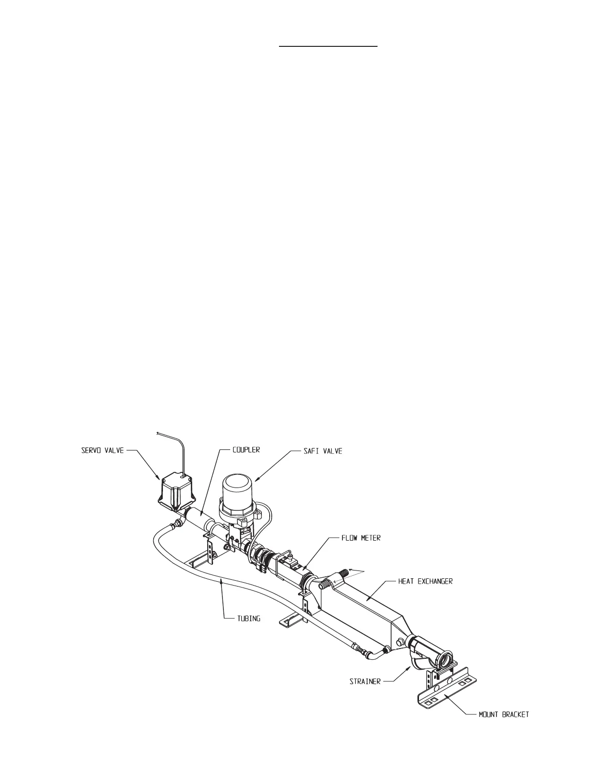
Liquifier Installation
Liquifier Installation
PRE-INSTALLATION: Remove the Liquifier plumbing panel from
the shipping board. The Liquifier plumbing panel has been
packaged with the "strainer end" mounting bracket in a shipping
position. Before installing the unit on your applicator, move this
bracket to the other side (inlet side) of the strainer to allow access
to strainer clean-out plug for cleaning. After repositioning
bracket, make sure all three brackets rest on a flat surface. If
necessary, loosen all six carriage bolts (two per bracket) at base of
brackets to allow all brackets to rest flat on mounting surface of
tool bar. Tighten carriage bolts only after insuring that all three
brackets rest on bar and unit does not "teeter" on center bracket.
LIQUIFIER KIT INSTALLATION: Remove any existing metering
valves. If the old metering valve has a built-in manifold, it is
recommended to install a separate new manifold for the Liquifier
k
it. Another option, although not recommended, is to use the
existing manifold, making certain the old metering valve is in the
maximum open position to allow for minimal restriction of flow
through the plumbing. There should not be any positive shut-off
valves installed in the plumbing between the Liquifier kit shut-off
valve and the knives.
Install the plumbing panel on the tool bar frame using the
carriage bolts and flange lock nuts through the top and bottom
brackets of the system. Trim any excess length off the bolts if
required. Attach the hose from the breakaway coupler to the
strainer inlet. Check for proper hose length for operation of the
disconnect mechanism of the breakaway coupler. Connect the
manifold hose to the servo valve outlet. Check for proper hose
length to avoid kinking at the hinge points.
LIQUIFIER VAPOR TUBE INSTALLATION: Locate the 1/2" EVA
vapor hose supplied with the kit. Starting on one half of the tool
bar, connect the 1/2" hose to the outside steel vapor tube. Route
the hose up the shank and along the tool bar frame to the inside
steel vapor tube. Allow enough extra hose to avoid kinking at the
hinge points. Cut the hose to length and attach to inside steel
vapor tube. Install a 11/2" x 3/4" x 1/2" tee fitting approximately
half w
ay along this hose between outside and inside steel vapor
tubes. SEE ILLUSTRATION BELOW.
L
ocate the 3/4" EVA hose supplied with the kit. Connect one end
to the 1/2" x 3/4" x 1/2" tee fittings and route along the tool bar
frame to the vapor outlet connections on the Liquifier. SEE
ILLUSTRATION BELOW. Allow enough extra hose to avoid kinking
at hinge points. Secure all hoses with properly sized hose clamps.
Secure the hoses to the tool bar frame with cable ties.
INSTALLATION NOTE: It is recommended to use an NH3
compatible thread sealing compound on all pipe thread
fittings.

 Loading...
